Silicon wafer cutting machine

A silicon wafer cutting and cutting machine technology, which is applied to fine working devices, stone processing equipment, manufacturing tools, etc., can solve the problems of poor ability of sticky tape cutting abrasive fluid, affecting the production efficiency of cutting silicon wafers, etc., to increase the hardness , Improve the cutting effect, improve the effect of cutting ability

Inactive Publication Date: 2014-04-09
FORTUNATE SOLAR TECH JIANGSU CO LTD
View PDF10 Cites 2 Cited by
  • Summary
  • Abstract
  • Description
  • Claims
  • Application Information

AI Technical Summary

Problems solved by technology

The existing steel wire for cutting silicon wafers is a high-strength steel wire coated with copper-zinc alloy on the surface. Its surface is smooth, and its ability to stick to cutting abrasive fluid is poor, which affects the production efficiency of cutting silicon wafers.

Method used


Image

  • Silicon wafer cutting machine

Examples


Embodiment Construction

[0012] The present invention is further described below.

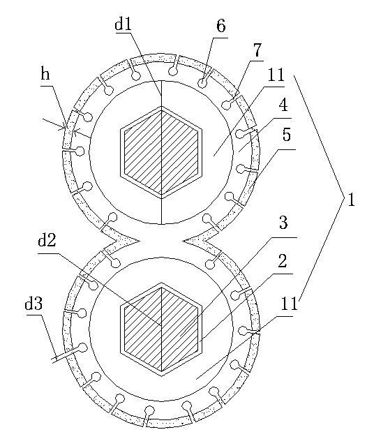
[0013] As shown in the figure, a silicon wafer cutting machine includes a silicon wafer cutting steel wire 1. The silicon wafer cutting steel wire 1 includes two steel wire bodies 11, and the diameter d1 of the steel wire body 11 is 0.3-0.6mm. The two steel wire bodies 11 are an integrated structure that is superimposed on each other to form an "8" shape. The steel wire body 11 is provided with a channel 2. The cross-sectional shape of the channel 2 is a regular hexagon, and the diameter d2 of its circumscribed circle is 0.15- 0.25mm, the channel 2 is filled with hard alloy 3, the outer surface of the steel wire body 11 is covered with a protective layer 4 made of high manganese steel, the thickness h of the protective layer 4 is 0.2-0.3mm, The surface of the protective layer is frosted 5, the protective layer 4 is provided with a liquid storage bag 6, the liquid storage bag 6 is a spherical structure, and the outer wa...


PUM

PropertyMeasurementUnit
diameteraaaaaaaaaa
diameteraaaaaaaaaa
diameteraaaaaaaaaa

Abstract

The invention relates to a silicon wafer cutting machine comprising a silicon wafer cutting wire. The silicon wafer cutting wire comprises two wire bodies which are mutually overlapped to be of an integrated structure shaped like an Arabic number '8', wherein channels are arranged inside the wire bodies; the cross section of each channel is in a regular hexagon shape; the channels are filled with hard alloy; the outer surface of each wire body is wrapped with a protective layer made of high manganese steel; the surfaces of the protective layers are polished; each protective layer is internally provided with liquid storage bags of a spherical structure; a cylindrical channel is arranged directly between each liquid storage bag and the outer wall of the corresponding protective layer. The cutting grinding liquid adhesion capacity of the silicon wafer cutting wire is improved, and the production efficiency is improved greatly.

Description

technical field [0001] The invention relates to a silicon wafer cutting machine. Background technique [0002] At present, silicon wafer cutting machines use high-strength steel wires that show copper-plated zinc alloys when cutting silicon wafers. When the steel wire is running at high speed, it sticks to the cutting abrasive fluid, and under a certain force, the abrasive material driven by the steel wire and the silicon rod are ground and cut, and finally silicon wafers are made. The existing steel wire for cutting silicon wafers is a high-strength steel wire coated with copper-zinc alloy on the surface. The surface is smooth, and the ability to stick to cutting abrasive fluid is poor, which affects the production efficiency of cutting silicon wafers. Contents of the invention [0003] The technical problem to be solved by the present invention is to provide a silicon chip cutting machine in view of the above disadvantages, wherein the silicon chip cutting steel wire ad...

Claims


Application Information

Patent Timeline
Patent Type & Authority Applications(China)
IPC IPC(8): B28D5/04
Inventor 聂金根
Owner FORTUNATE SOLAR TECH JIANGSU CO LTD
Why Eureka
Try Eureka