Silicon carbide ceramic heat exchanger

A technology of silicon carbide ceramics and heat exchangers, applied in the direction of heat exchanger types, heat exchanger shells, indirect heat exchangers, etc., can solve problems such as equipment failure, small thermal expansion coefficient, and thermal conductivity limiting heat exchange efficiency. Achieve the effects of low replacement times and costs, consistent thermal expansion coefficients, and remarkable energy-saving effects

Active Publication Date: 2015-06-24
山东宝纳新材料有限公司
View PDF7 Cites 2 Cited by
  • Summary
  • Abstract
  • Description
  • Claims
  • Application Information

AI Technical Summary

Problems solved by technology

[0004] Chinese patent document CN101526317A (application number 200910135702.X) discloses a block-hole graphite heat exchanger, which realizes heat exchange by processing vertical, horizontal, and non-interconnected channels on the graphite block, but the processing is complicated, and the vertical and horizontal channel walls Once damaged, the heat exchange fluid will be mixed and the equipment will fail, making it impossible to repair and reuse;
[0005] Chinese patent document CN102840775A (application number 201210210819.1) discloses a uniformly arranged graphite tube-type graphite heat exchanger, but as we all know, although the theoretical thermal conductivity of graphite is very high, the thermal conductivity of general block graphite is only 5-20W / (m.K), the low thermal conductivity limits the heat transfer efficiency, and the graphite strength is low, it is easy to be damaged during use, and the service reliability is poor
However, most heat exchangers work at higher temperatures, and it is difficult and costly to prepare silicon carbide ceramic shells, which is obviously not feasible
The thermal expansion coefficient of silicon carbide ceramics is small. At higher temperatures, the expansion and contraction difference between the silicon carbide tube bundle and the shell due to the difference in thermal expansion coefficient will easily lead to the sealing failure of the connecting tube plate as the tube shell elongates. Taking stainless steel SUS304 as an example, from From 20°C to 200°C, the coefficient of thermal expansion is about 16.8×10 -6 / °C, while the thermal expansion coefficient of the silicon carbide ceramic tube at the same temperature is only 4.2×10 -6 / °C, taking a 2m-long heat exchanger as an example, from 20°C to 200°C, the elongation difference between the stainless steel shell and the silicon carbide ceramic tube is about 2.26mm, such a large difference in expansion and contraction will inevitably lead to seal failure

Method used


Image

  • Silicon carbide ceramic heat exchanger
  • Silicon carbide ceramic heat exchanger

Examples


Embodiment 1

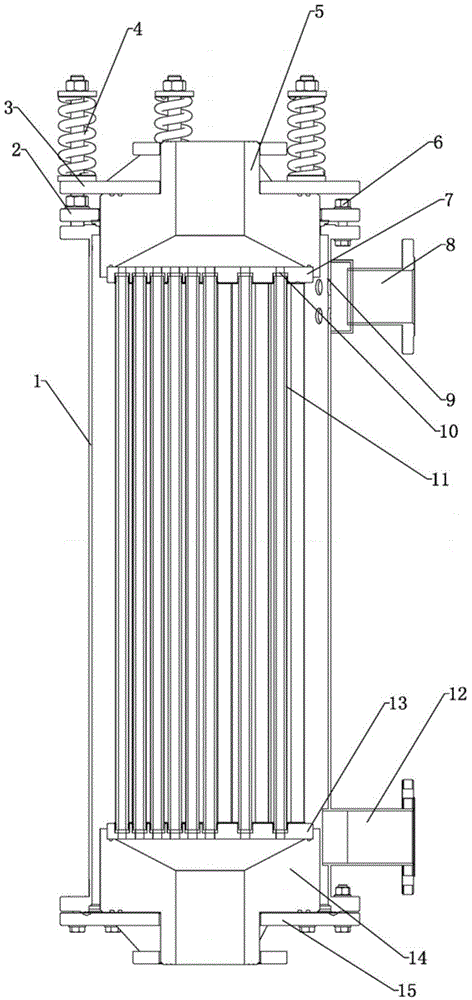
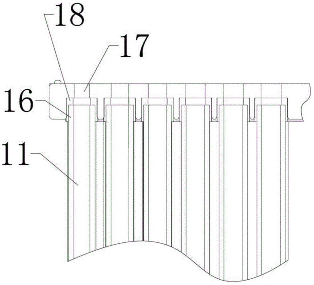
[0026] like Figure 1-2 The silicon carbide ceramic heat exchanger shown includes a silicon carbide ceramic upper blocking plate 7, a silicon carbide ceramic lower blocking plate 13, a silicon carbide ceramic heat exchange tube bundle 11, an upper collecting port 5, a lower collecting port 14 and a stainless steel shell 1 , the silicon carbide ceramic heat exchange tube bundle 11 is arranged in the shell 1, the silicon carbide ceramic upper blocking plate 7 and the silicon carbide ceramic lower blocking plate 13 are provided with stepped holes 10, and the silicon carbide ceramic heat exchange tube bundle 10 is The hole diameter on one side of 11 is larger than the hole diameter on the other side. The two ends of the silicon carbide ceramic heat exchange tube bundle 11 are respectively connected to the upper blocking plate 7 of silicon carbide ceramics and the lower blocking plate 13 of silicon carbide ceramics through the stepped holes 10. The blocking plate 7 is connected wit...

Embodiment 2

[0035]A silicon carbide ceramic heat exchanger, comprising a silicon carbide ceramic upper blocking plate 7, a silicon carbide ceramic lower blocking plate 13, a silicon carbide ceramic heat exchange tube bundle 11, an upper collection port 5, a lower collection port 14 and a shell 1, the The silicon carbide ceramic heat exchange tube bundle 11 is arranged in the shell 1, the silicon carbide ceramic upper blocking plate 7 and the silicon carbide ceramic lower blocking plate 13 are provided with stepped holes 10, and the silicon carbide ceramic heat exchange tube bundle 10 described in the stepped hole 11— The aperture on one side is larger than the aperture on the other side, and the two ends of the silicon carbide ceramic heat exchange tube bundle 11 are respectively connected to the upper blocking plate 7 of silicon carbide ceramics and the lower blocking plate 13 of silicon carbide ceramics through the stepped holes 10, and the upper blocking plate of silicon carbide ceramics...


PUM


Abstract

The invention relates to a silicon carbide ceramic heat exchanger. The silicon carbide ceramic heat exchanger comprises a silicon carbide ceramic upper blocking plate, a silicon carbide ceramic lower blocking plate, a silicon carbide ceramic heat exchange tube bundle, an upper collection opening, a lower collection opening and a shell, wherein the silicon carbide ceramic heat exchange tube bundle is arranged inside the shell; step holes are formed in the silicon carbide ceramic upper blocking plate and the silicon carbide ceramic lower blocking plate; the aperture of each step hole in one side of the silicon carbide ceramic heat exchange tube bundle is more than the aperture of the step hole in the other side of the silicon carbide ceramic heat exchange tube bundle; the both ends of the silicon carbide ceramic heat exchange tube bundle are respectively connected with the silicon carbide ceramic upper blocking plate and the silicon carbide ceramic lower blocking plate through the step holes. According to the silicon carbide ceramic heat exchanger provided by the invention, the existing connection relationship between the silicon carbide ceramic heat exchange tube bundle, and the silicon carbide ceramic upper blocking plate and the silicon carbide ceramic lower blocking plate is changed, so that the problem of sealing invalidation which is caused by different expansion degrees due to cold and heat non-uniformity of the silicon carbide ceramic heat exchange tube bundle, the silicon carbide ceramic upper blocking plate, the silicon carbide ceramic lower blocking plate and the shell can be solved.

Description

technical field [0001] The invention relates to a silicon carbide ceramic heat exchanger, which belongs to the technical field of inorganic non-metallic materials. Background technique [0002] A heat exchanger is a device that transfers (part of) heat from a hot fluid to a cold fluid, and is widely used in metallurgy, petroleum, chemical, electric power, food, pharmaceutical and other fields. [0003] Pickling is an important process in the steel rolling production process, and the temperature of the acid has a significant impact on the pickling effect. Taking hydrochloric acid pickling as an example, with the same concentration of hydrochloric acid, when the temperature is increased from 18°C ​​to 60°C, the pickling speed can be increased by nearly 10 times. Therefore, high-efficiency, energy-saving and safe hydrochloric acid heating process and equipment are of great significance for steel rolling production. It is an effective way to use high-temperature water vapor to...

Claims


Application Information

Patent Timeline
Patent Type & Authority Patents(China)
IPC IPC(8): F28D7/16F28F9/04F28F21/04
Inventor 张玉军李兆敏李其松孙海滨宋建锋
Owner 山东宝纳新材料有限公司
Why Eureka
Try Eureka