A rake structure thermal flow field measurement device

A measuring device and structural heat technology, applied in measuring devices, fluid velocity measurement, velocity/acceleration/impact measurement, etc., can solve the problems of lack of fast and accurate measurement methods, and achieve convenient maintenance, high sensitivity, and intuitive data Effect

Inactive Publication Date: 2017-06-27
NANJING UNIV OF AERONAUTICS & ASTRONAUTICS
View PDF5 Cites 0 Cited by
  • Summary
  • Abstract
  • Description
  • Claims
  • Application Information

AI Technical Summary

Problems solved by technology

[0002] In the field of low-velocity air flow field measurement, at present, there is no fast and accurate measurement method

Method used


Image

  • A rake structure thermal flow field measurement device
  • A rake structure thermal flow field measurement device
  • A rake structure thermal flow field measurement device

Examples


Embodiment 1

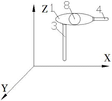
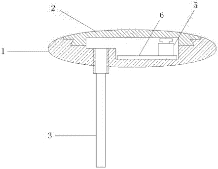
[0043] Such as Figure 1~2 As shown, this product is a rake structure flow field measurement device. This product includes several thermal velocity probes 3 and airflow temperature probes 4. The thermal velocity probes are fixed in a linear array on the fixed bracket 1. The fixed bracket 1 is An elliptical cylinder, the array of thermal velocity probes 3 is located on the short axis plane of the elliptical cylinder of the fixed bracket 1, the airflow temperature probe 4 is fixed on the long axis plane of the fixed bracket, and forms an angle of 90° with the thermal velocity probe 3, Such as Figure 2~3 As shown, the fixed bracket includes a fixed bracket body and a fixed bracket cover plate 2, a PCB circuit board 6 is fixed inside the fixed bracket body, and a terminal 5 is welded on the PCB circuit board 6, and the data line of the thermal speed probe 3 passes through the wiring The terminal 5 is connected to the PCB circuit board 6, and a hub terminal is also arranged on th...

Embodiment 2

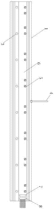
[0057] This embodiment is a traditional rake-shaped structure flow field measurement device using a thermometer, including a fixed bracket 1, a thermometer 12, and a metal casing 13, such as Figure 8 As shown, the thermometer is installed inside the metal casing 13, and seven metal casings are installed in a linear array on the fixed bracket 1. The initial temperature of the metal casing 13 is obtained by measuring the thermometer. After the fixed bracket 1 moves in the three-dimensional driving device, measure The temperature drop of the metal casing 13 is obtained, and thus the velocity of the fluid is also obtained through calculation.

Embodiment 3

[0059] This embodiment is another implementation of the rake structure flow field measurement device. This embodiment includes a support plate 14, on which a number of parallel elongated through-holes are arranged, and through the elongated through-holes To produce the effect of the airflow channel, the thermal velocity probe 3 is embedded in the support plate 14, and is arranged between two adjacent elongated through holes, the support plate 14 is installed on the fixed bracket 1, and the circuit part is the same as that of the first embodiment , such a structure has poor maintainability, but improves the integrity and is convenient for use and cleaning.


PUM


Abstract

The invention discloses a rake structure thermal flow field measurement device, which comprises a rake measurement fixed bracket, a plurality of thermal velocity probes installed at equal intervals, a fluid flow field temperature probe, a three-dimensional drive device controlled by a computer, and a computer controlled flow field. The measuring device moves and locates in the three-dimensional space along the X, Y, and Z axes, and the data acquisition system collects the gas velocity at the coordinate points of each velocity probe on the array rack in a specified position in the three-dimensional space within the movable range. The flow field processing software processes the collected data to generate one-dimensional, two-dimensional and three-dimensional airflow velocity diagrams; the invention has the characteristics of being easy to use and high measurement accuracy.

Description

technical field [0001] The invention relates to a flow field measurement device, in particular to a rake structure thermal flow field measurement device for low velocity air flow field measurement. Background technique [0002] In the field of low-velocity air flow field measurement, at present, there is no fast and accurate measurement method. With the emphasis on the quality research of the air in confined spaces with people, such as spacecraft, aircraft cabins, high-speed train compartments, ship cabins, stadiums, etc., it is necessary to pay attention to the direction and size of the airflow in the confined space, that is, the airflow. Therefore, it is necessary to accurately measure the airflow velocity and airflow direction. Contents of the invention [0003] The invention provides a measuring device that can quickly and accurately measure the flow field of low-velocity airflow. By moving the measuring device, the airflow velocity conditions of relevant planes and s...

Claims


Application Information

Patent Timeline
Patent Type & Authority Patents(China)
IPC IPC(8): G01P5/00G01P13/02G01P1/00
Inventor 孙卫平朱春玲陈文虎范涛峰张泉史素青
Owner NANJING UNIV OF AERONAUTICS & ASTRONAUTICS
Why Eureka
Try Eureka