
Oscilloscope having delayed trigger function

An oscilloscope and delay time technology, applied in the direction of digital variable display, etc., to achieve the effects of precise delay time, diversified trigger methods, and improved trigger accuracy

Active Publication Date: 2014-04-09
RIGOL
View PDF7 Cites 10 Cited by
  • Summary
  • Abstract
  • Description
  • Claims
  • Application Information

AI Technical Summary

Problems solved by technology

There are many types of existing triggers, which will not be described here. However, none of the existing oscilloscopes can implement triggering based on the time relationship between any two measured signals.

Method used


Image

  • Oscilloscope having delayed trigger function
  • Oscilloscope having delayed trigger function
  • Oscilloscope having delayed trigger function

Examples


example 1

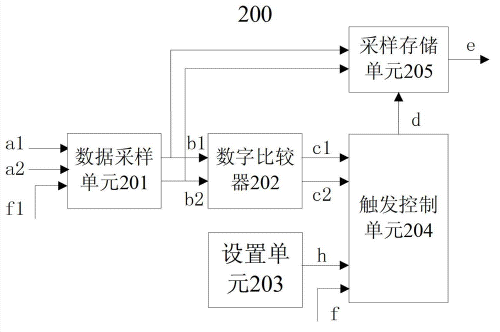
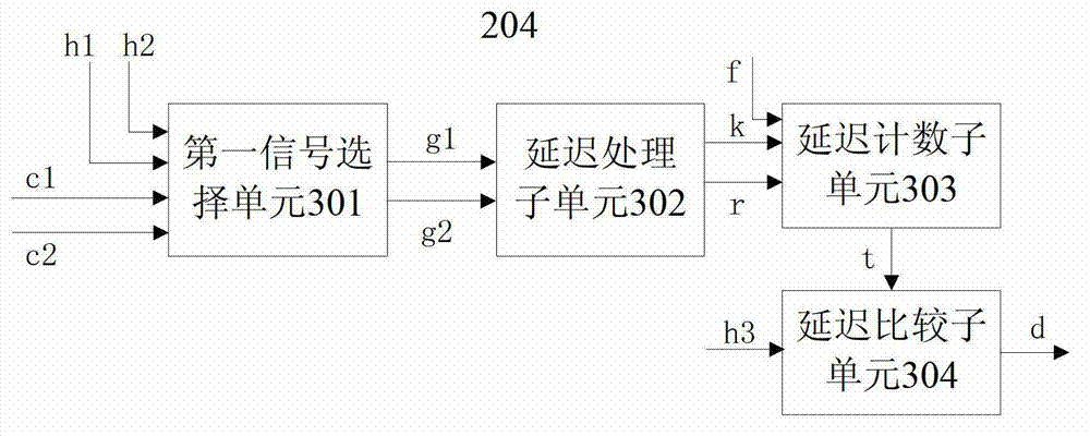
[0092] refer to figure 2 , the data sampling unit 201 includes two ADCs, according to the sampling clock f1, samples the two-way measured signals a1 and a2 respectively, and generates one-way first sampling data b1 and one-way second sampling data b2; the digital comparison unit 202 includes two The digital comparator performs level comparison processing on one channel of first sampled data b1 and one channel of second sampled data b2 to generate corresponding one channel of first comparison signal c1 and one channel of second comparison signal c2; at this time, the clock f is Sampling the clock f1, the trigger control unit 204 obtains the delay time t from the first comparison signal c1 and the second comparison signal c2 according to the sampling clock f1, delay order and edge type. It can be seen that when the data sampling unit 201 samples a channel of the signal to be tested and generates a channel of serial low-speed sampling data, for example, the sampling clock is 125...

example 2

[0100] refer to figure 2 , the data sampling unit 201 samples the two-way measured signals a1 and a2 respectively according to the sampling clock f1 to generate parallel n-way first sampling data b1, parallel n-way second sampling data b2 and a trigger clock f2; The comparison unit 202 performs level comparison processing on n channels of first sampling data b1 and n channels of second sampling data b2, respectively, to generate parallel n channels of first comparison signals c1 and parallel n channels of parallel second comparison signals c2; at this time, The clock f is the trigger clock f2, and the trigger control unit 204 obtains the delay time t from the parallel n-way first comparison signal c1 and the parallel n-way second comparison signal c2 according to the trigger clock f2, the delay sequence and the edge type .

[0101] In the second example, the sampling clock f1 may include M sampling clocks f1 (1~M) with the same frequency and different phases, and the data sa...


PUM


Abstract

Provided in the invention is an oscilloscope having the delayed trigger function. The oscilloscope comprises: a data sampling unit, which is used for carrying out sampling on two paths of tested signals so as to generate first sampling data and second sampling data; a digital comparison unit, which is used for carrying out level comparison processing on the first sampling data and the second sampling data so as to generate a first comparison signal and a second comparison signal; a setting unit, which is used for setting a delay sequence, an edge type, and a delay time range; a trigger control unit, which is used for obtaining delay time between the two paths of tested signals by the first comparison signal and the second comparison signal according to the clock, the delay sequence and the edge type and generating a trigger signal when the delay time is in the delay time range. According to the invention, triggering can be realized based on the time relation between any two paths of tested signals; and because the delay time is obtained from the digital first comparison signal and the digital second comparison signal, so that delayed triggering is realized by using the digital way.

Description

technical field [0001] The invention relates to the technical field of test and measurement, in particular to an oscilloscope with a delayed trigger function. Background technique [0002] Oscilloscope is an electronic measuring instrument with a wide range of uses. It can convert electrical signals invisible to human eyes into waveform images visible to human eyes, which is convenient for people to study the changing process of various electrical signals. The traditional analog oscilloscope uses an analog circuit (oscilloscope), and its electron gun emits electrons to the screen. The emitted electrons are focused to form an electron beam, and hit the screen with a fluorescent substance on the inner surface, so that the point hit by the electron beam is Light is emitted, which traces a wavy curve. Digital storage oscilloscopes (DSO), referred to as digital oscilloscopes, convert the measured signal into digital information through an analog-to-digital converter and store it...

Claims


Application Information

Patent Timeline
Patent Type & Authority Applications(China)
IPC IPC(8): G01R13/02
Inventor 龚桂强王悦王铁军李维森
Owner RIGOL
Learn More