Demodulation device based on orbital angular momentum of light beams

A technology of orbital angular momentum and demodulation device, which is applied in the direction of light demodulation, optics, instruments, etc., can solve the problems of insufficient recovery of phase information, increased possibility of demodulation errors, and reduced communication reliability. Achieve the effects of reducing the possibility of demodulation errors, simple structure, and low cost

Inactive Publication Date: 2014-04-09
SUN YAT SEN UNIV
View PDF3 Cites 22 Cited by
  • Summary
  • Abstract
  • Description
  • Claims
  • Application Information

AI Technical Summary

Problems solved by technology

"Phase-shift interference-based wavefront characterization for orbital angular momentum modes" published in "Optics Letters" in 2013 proposed to use two reference light with a phase difference of π / 2 and orbital angular momentum mode interference to obtain two interference pattern, the phase of the orbital angular momentum mode is recovered through these two interference patterns, but the phase in a large area near the central singularity is blurred, and the phase information near the singularity is not fully recovered, that is, for the demodulation of the orbital angular momentum mode Incomplete, which increases the possibility of demodulation errors, increases the bit error rate, and reduces the reliability of communication

Method used


Image

  • Demodulation device based on orbital angular momentum of light beams
  • Demodulation device based on orbital angular momentum of light beams
  • Demodulation device based on orbital angular momentum of light beams

Examples


Embodiment 1

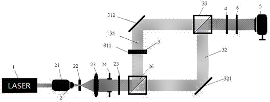
[0028] Such as Figures 1 to 2 Shown is the first embodiment of the present invention based on beam orbital angular momentum demodulation device, which includes laser 1, first modulation module 2, angular momentum generation module 3, second modulation module 4, The demodulation module 5, the laser 1 outputs parallel beams, the beams pass through the first modulation module 2, the angular momentum generation module 3, the second modulation module 4, and the demodulation module 5 to form an optical path, and the demodulation module 5 and the second modulation module 4 is provided with an interferometric module 6 that can be placed movably for generating an interferometric image. Specifically, the first modulation module 2 for modulating the light beam emitted by the optical laser 1 includes an objective lens 21, a pinhole device 22, a lens 23, a diaphragm 24, and a first polarizer 25 arranged in sequence, and the light beam emitted by the laser 1 can be sequentially arranged. ...

Embodiment 2

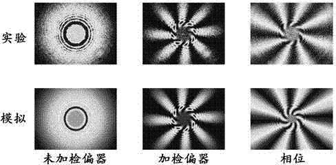
[0037] Such as image 3 Shown is the second embodiment of the present invention based on the optical beam orbital angular momentum demodulation device and its application method. This embodiment is similar to the first embodiment, except that the topological charge value m is 8 in this embodiment.


PUM


Abstract

The invention relates to devices in the field of photoelectric technologies and in particular relates to a demodulation device based on orbital angular momentum of light beams. The demodulation device comprises a laser, a first modulation module, an angular momentum generation module, a second modulation module and a demodulation module, wherein the laser is used for outputting light beams parallel to each other; the light beams pass through the first modulation module, the angular momentum generation module, the second modulation module and the demodulation module to form a light path; and an interference module, arranged movably and used for generating interference images, is arranged between the demodulation module and the second modulation module. The interference module is used for generating a symmetrical petal interference pattern to obtain a topological charge value and restore phases of the orbital angular momentum by using a light intensity formula; due to quality detection of an interference pattern passing through a polarization analyzer and a light spot pattern not passing through the polarization analyzer, phases near a singular point in an orbital angular momentum mode phase can be restored; demodulation error probability can be reduced; error rate is reduced; and communication reliability is improved.

Description

technical field [0001] The present invention relates to devices in the field of optoelectronic technology, and more specifically, to a demodulation device based on beam orbital angular momentum. Background technique [0002] The orbital angular momentum mode is a propagation mode with a vortex phase factor eimφ. The phase vortex makes it have optical orbital angular momentum, a physical characteristic parameter that other modes do not have. It is useful in the fields of communication and micro-nano photonics Important research and application value, has become a research hotspot in recent years. [0003] "Terabit-scale Orbital Angular Momentum Mode Division Multiplexing in Fibers" published in "Science" in 2013 confirmed the feasibility of orbital angular momentum mode multiplexing. The designer designed a special optical fiber that supports two orbital angular momentum modes to be multiplexed at ten wavelengths, can transmit 1.1km, and has a bandwidth of 1.6Tbps. It provid...

Claims


Application Information

Patent Timeline
Patent Type & Authority Applications(China)
IPC IPC(8): G02F2/00
Inventor 孙华阳谢向生杨良信周建英
Owner SUN YAT SEN UNIV
Why Eureka
Try Eureka