Power split hybrid system mode switching hardware-in-the-loop simulation test bench

A hybrid power system and mode switching technology, applied in electrical testing/monitoring, etc., can solve problems such as difficulty, complex control strategy, and cumbersome configuration process, and achieve the effects of accurate prediction and evaluation, shortened development time, and improved execution efficiency

Active Publication Date: 2014-04-09
TONGJI UNIV
View PDF4 Cites 19 Cited by
  • Summary
  • Abstract
  • Description
  • Claims
  • Application Information

AI Technical Summary

Problems solved by technology

The most important aspect of the control of the hybrid power system is that the smoothness of the vehicle is optimized during the mode switching process, and the impact is minimized. For the mode switching of the system, especially the switching from pure electric power to the hybrid power mode with engine intervention, wet brakes are involved. The process of separation and combination and the coordinated control of the torque of the generator, motor, and engine, especially the control of the power split transmission mechanism with a special structure such as planetary row coupling, the control strategy is complex and difficult, and the domestic power split hybrid system mode The research on the switching control strategy is still in its infancy, and most of them are offline simulations by establishing mathematical models of the mode switching control system, which cannot reflect the different dynamic response characteristics of

Method used


Image

  • Power split hybrid system mode switching hardware-in-the-loop simulation test bench
  • Power split hybrid system mode switching hardware-in-the-loop simulation test bench
  • Power split hybrid system mode switching hardware-in-the-loop simulation test bench

Examples


Example Embodiment

[0039] The present invention will be described in detail below with reference to the drawings and specific embodiments. This embodiment is implemented on the premise of the technical solution of the present invention, and a detailed implementation mode and specific operation process are given, but the protection scope of the present invention is not limited to the following embodiments.

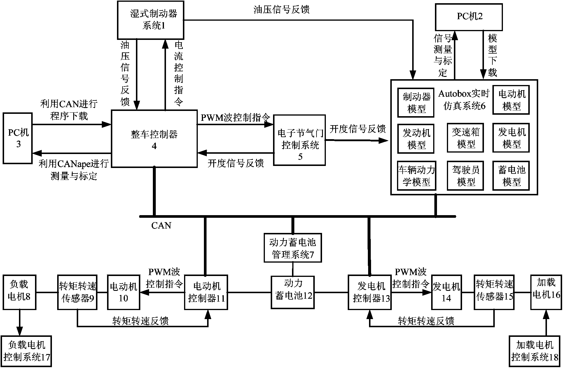
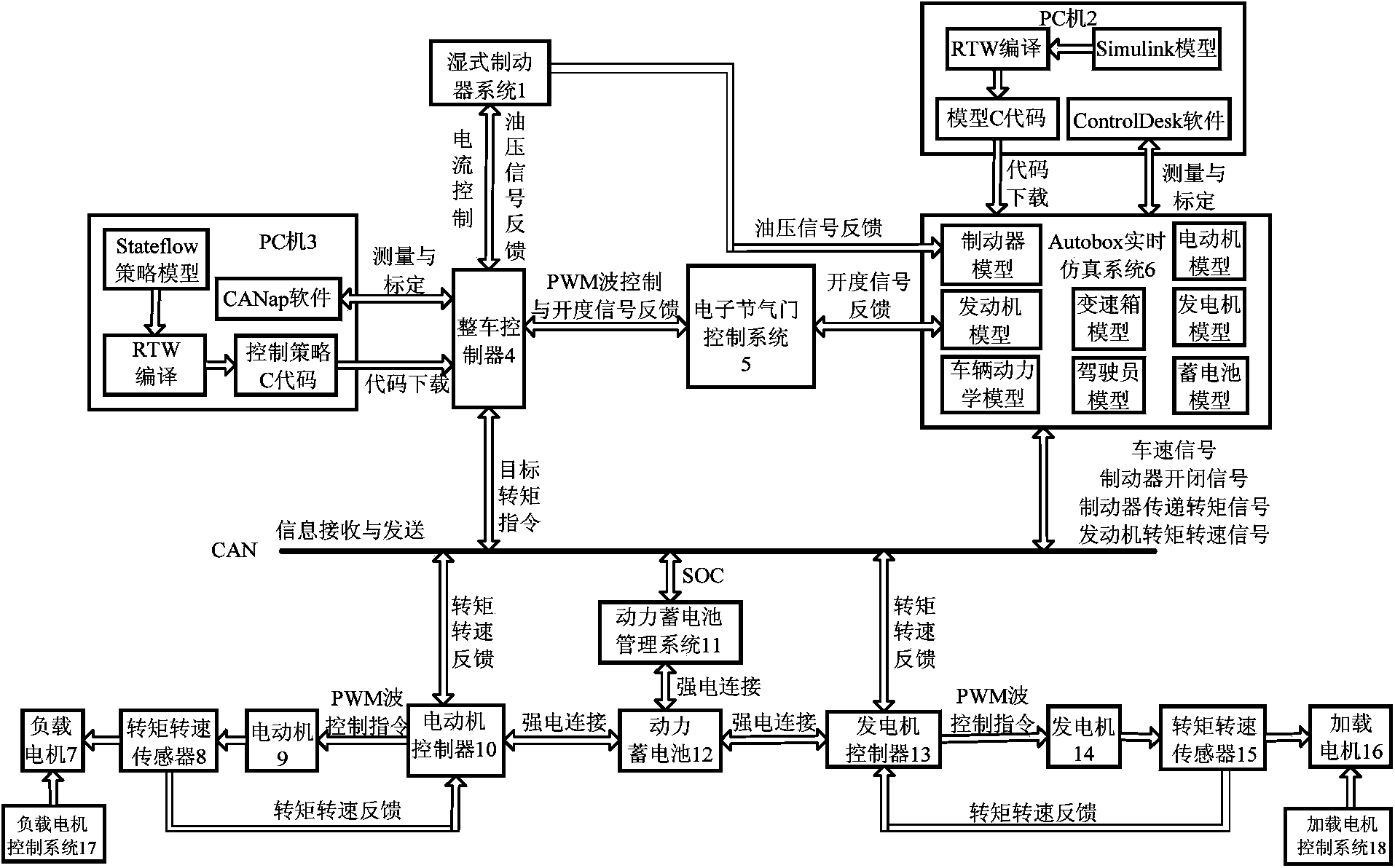
[0040] Such as figure 1 , figure 2 As shown, a power split hybrid power system mode switching semi-physical hardware-in-the-loop simulation test bed, including wet brake system 1, PC 2 and 3, vehicle controller 4, electronic throttle control system 5, AutoBox real-time simulation system 6. Power battery 12 and power battery management system 11, electric motor 9 and motor controller 10, generator 14 and generator controller 13, torque and speed sensors 8 and 15, load motor 7 and load motor control system 17, load motor 16 and load motor control system 18. The vehicle controller 4 is respective...


PUM


Abstract

The invention relates to a power split hybrid system mode switching hardware-in-the-loop simulation test bench. The power split hybrid system mode switching hardware-in-the-loop simulation test bench includes a PC, a finished automobile controller, an AutoBox real-time simulation system and an actual automobile actuator system, wherein the PC is connected with the finished automobile controller and the AutoBox real-time simulation system respectively, and the actual automobile actuator system is connected with the finished automobile controller and the AutoBox real-time simulation system respectively; the AutoBox real-time simulation system acquires signals of the actual automobile actuator system in real time and transmits output signals to the finished automobile controller; the finished automobile controller judges the operating states of a finished automobile according to the signals transmitted by the actual automobile actuator system and the AutoBox real-time simulation system; and the AutoBox real-time simulation system receives feedback signals of the actual automobile actuator system and performs model simulation operation, and mode switching is completed. Compared with the prior art, the power split hybrid system mode switching hardware-in-the-loop simulation test bench of the invention has the advantage that the power split hybrid system mode switching hardware-in-the-loop simulation test bench can improve the development efficiency of power split hybrid system mode switching control strategies.

Description

technical field [0001] The invention relates to a power system hardware-in-the-loop simulation test bench, in particular to a power split hybrid power system mode switching hardware-in-the-loop simulation test bench. Background technique [0002] The power split hybrid system (Power Split Hybrid System) is composed of a planetary row coupling mechanism, a generator, an electric motor, an engine, a battery, an inverter, a wet brake or a clutch, etc. The engine passes through the power split mechanism (planetary row), a part of the power directly drives the vehicle through the mechanical path, and the other part of the power drives the vehicle through the electric power path. The power ratio of the two can be adjusted according to the driving road conditions. When the vehicle speed is low, the electric power path is the main path to optimize the engine working area; when the vehicle speed is high, the mechanical path is the main path to obtain higher transmission efficiency. ...

Claims


Application Information

Patent Timeline
IPC IPC(8): G05B23/02
Inventor 赵治国代显军王晨袁喜悦
Owner TONGJI UNIV
Why Eureka
Try Eureka