Hydrodynamic retarder and method for controlling the power transmission of such a retarder

A hydraulic reducer and power transmission technology, applied in the field of hydraulic reducer, can solve the problems of unfavorable heat exchanger, increased power loss of hydraulic reducer, high price, etc.

Active Publication Date: 2014-04-09
VOITH PATENT GMBH
View PDF5 Cites 9 Cited by
  • Summary
  • Abstract
  • Description
  • Claims
  • Application Information

AI Technical Summary

Problems solved by technology

That is to say, if the relatively small volume flow of working medium in non-braking operation is conveyed via a larger heat exchanger in braking operation, the air entrained by the working medium from the working chamber accumulates in the heat exchanger. On the one hand, this is detrimental to the heat exchanger, and on the other hand, when the gear unit is switched on, i.e. when transitioning from non-braked to braked operation, it can lead to emptying of the working chamber after the filling process has already started. The case of hair blowing (Leerblasen)
[0010] Naturally cost-intensive and expensive if an own "small" working medium circuit is designed with its own heat exchanger
[0011] In addition, practice has shown that the power loss of known hydrodynamic retarders, in which the working medium flows from a raised container into its working chamber during non-braking operation, increases significantly with the number of revolutions

Method used


Image

  • Hydrodynamic retarder and method for controlling the power transmission of such a retarder
  • Hydrodynamic retarder and method for controlling the power transmission of such a retarder
  • Hydrodynamic retarder and method for controlling the power transmission of such a retarder

Examples


Embodiment Construction

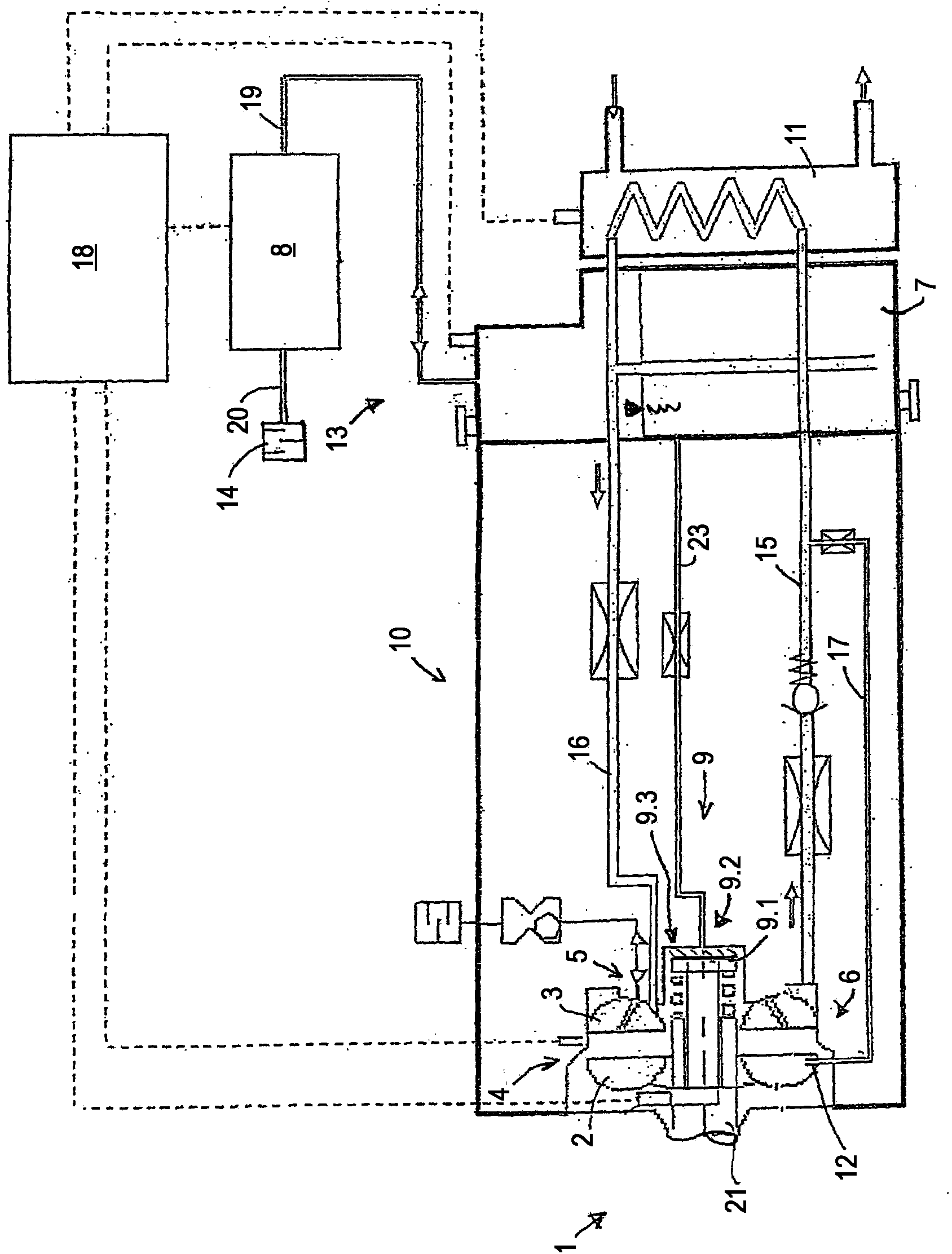
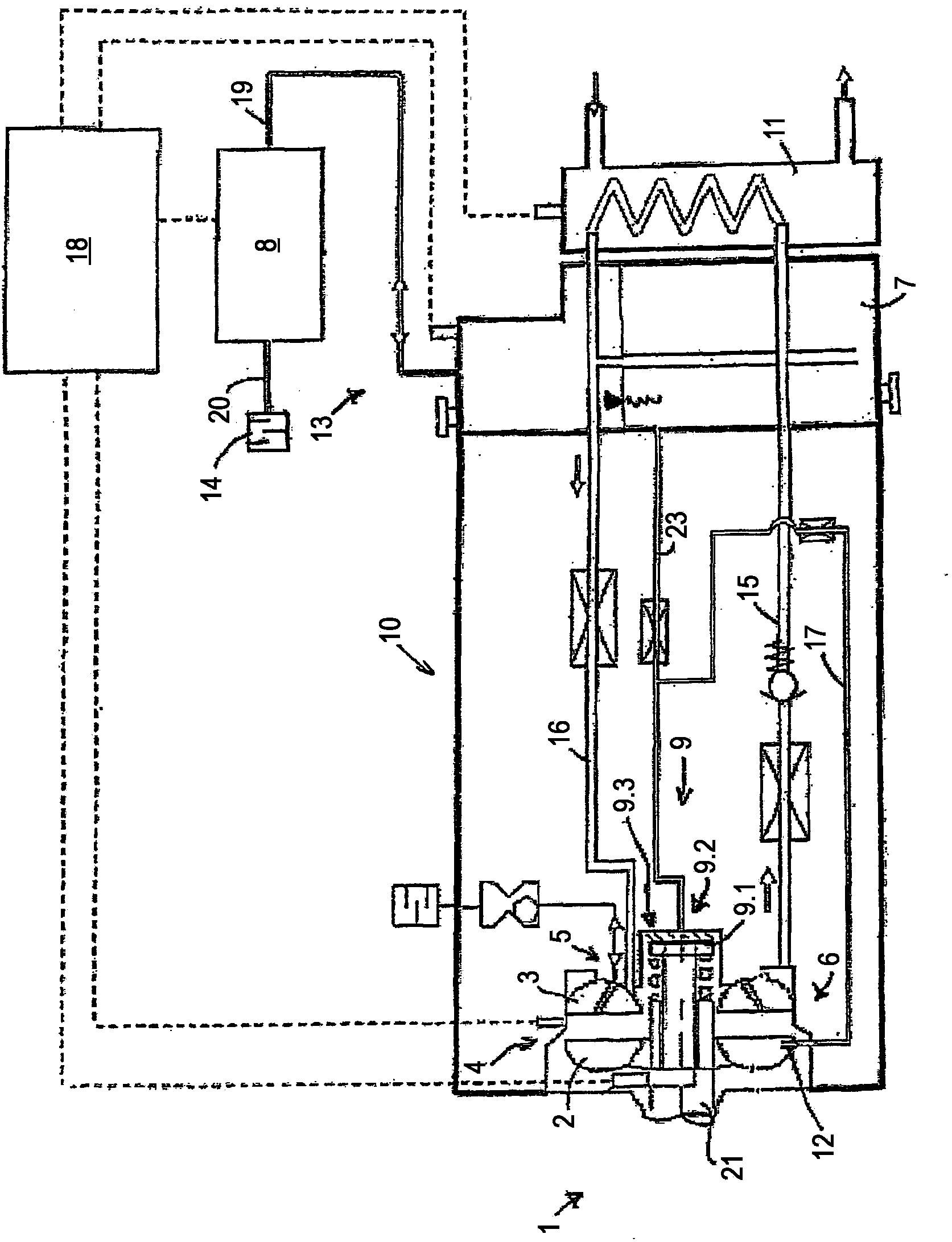
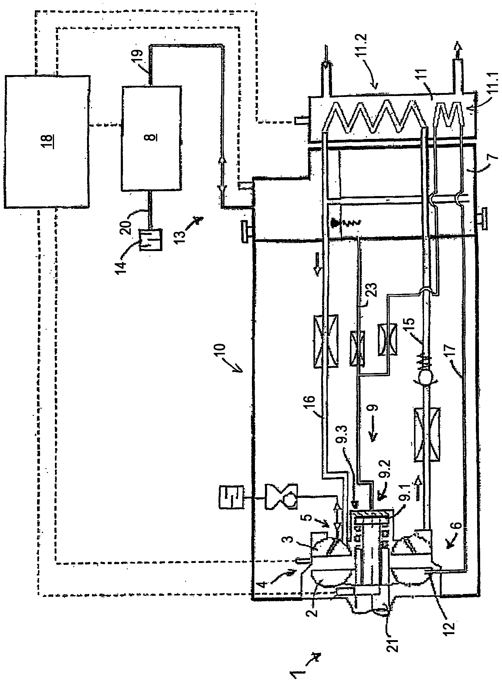
[0040] figure 1 Shown is a hydrodynamic retarder 1 as part of a brake system of a motor vehicle with a working medium-conducting external cooling circuit for dissipating the working medium during braking operation of the hydrodynamic retarder 1 accumulated heat. In the present case, the working medium is oil. However, the hydrodynamic retarder 1 can also be part of the cooling circuit of the vehicle, in which case the working medium can then be water or an aqueous solution.

[0041] as in figure 1 As shown in , in the external cooling circuit, the following components are arranged in the flow direction of the working medium: a hydrodynamic retarder 1, which includes a rotor 2 and a stator 3, which together form a torus-shaped working chamber 4 ; the opening of the first connecting line 15 from the hydraulic retarder 1 to the heat exchanger 11, also called an oil cooler when the working medium is oil; a fixed section with a constant cross section arranged behind the opening ...


PUM


Abstract

The invention relates to a method for controlling the power transmission of a hydrodynamic retarder, comprising a circulating rotor having vanes and a stator having vanes or a counter-rotating rotor having vanes circulating in the opposite rotational direction to the rotor, which together form a working chamber that can be filled with operating medium by means of an inlet and that can be emptied by means of an outlet, wherein the working chamber is filled in a brake operation with operating medium and a brake torque is generated with the hydrodynamic retarder and, in a non-braking operation, the working chamber is emptied to a specific residual amount of operating medium and substantially no brake torque is generated with the hydrodynamic retarder.; The invention is characterised by the following step: In the non-braking operation, by means of an idling pump, operating medium is conveyed from an operating medium reserve, which is provided outside the working chamber in an operating medium reserve tank, into the working chamber of the hydrodynamic retarder for the adjustment of the residual amount.

Description

technical field [0001] The invention relates to a method for controlling the power transmission of a hydrodynamic retarder and a hydrodynamic retarder, for example for a bus, truck or rail vehicle. [0002] The hydrodynamic retarder has a working chamber which can be filled with a working medium in order to transmit torque hydraulically from the driven primary impeller (rotor) to the stationary secondary impeller, which is therefore also called the stator. Instead of a static secondary impeller, it is also possible to provide a secondary impeller that rotates counter to the direction of rotation of the primary impeller, in order to form a counter-rotating gearbox. The working medium in the rotor is accelerated radially outwards by driving the rotor by means of the rotor shaft to be braked, for example the transmission output shaft, or indirectly a shaft (cardan shaft) which is connected in a rotationally fixed manner to the drive wheels of the motor vehicle And into the stato...

Claims


Application Information

Patent Timeline
Patent Type & Authority Applications(China)
IPC IPC(8): B60T1/087F16D57/04
CPCF16D57/04B60T10/02B60T1/087
Inventor 迪特尔·劳克曼维尔纳·亚当斯于尔根·基布勒
Owner VOITH PATENT GMBH
Why Eureka
Try Eureka