Movable CT machine

A mobile, transmission mechanism technology, applied in the field of medical equipment, can solve the problems of affecting the horizontal scanning accuracy of the mobile CT machine, affecting the motion accuracy, restricting the application space, etc., to achieve simple structure, improve imaging quality, and isolate external vibrations. Effect

Inactive Publication Date: 2014-04-16
SUZHOU INST OF BIOMEDICAL ENG & TECH +2
View PDF6 Cites 15 Cited by
  • Summary
  • Abstract
  • Description
  • Claims
  • Application Information

AI Technical Summary

Problems solved by technology

[0002] The weight of the existing mobile CT machine is about 350kg or more, and it is inconvenient to move when transferring and using, which seriously restricts its application space
In addition, the horizontal scanning motion of existing mobile CT machines generally adopts the crawler method, and the crawler directly touches the ground, which is easy to affect the motion accuracy due to the flatness of the ground, which in turn affects the horizontal scanning accuracy of the mobile CT machine, resulting in poor imaging quality

Method used


Image

  • Movable CT machine
  • Movable CT machine
  • Movable CT machine

Examples


Embodiment Construction

[0022] The present invention will be described in detail below with reference to the accompanying drawings and in combination with embodiments.

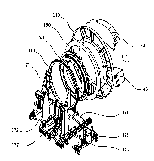
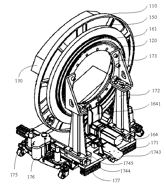
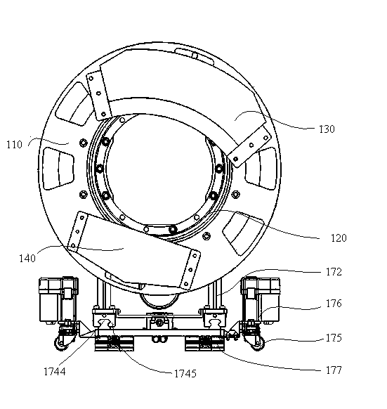
[0023] refer to Figure 1 to Figure 8 As shown, the mobile CT machine includes a detection mechanism 101, a transmission mechanism 160, a lateral movement mechanism 174, and a mobile fixing mechanism 170. 120 connections, the detector system 130 and the radiation source 140 are arranged on one side of the turntable 110, and the other side of the turntable 110 is fixedly connected with the slip ring 150 and the outer ring 122 of the bearing 120, The other side of the turntable 110 is also connected with the transmission mechanism 160, the transmission mechanism 160 is composed of a first pulley 161, a second pulley 162, a fixing member 1641, and a rotating motor 164. The first pulley 161 is connected to the turntable 110, the rotating motor 164 is fixedly connected to the inner ring 121 of the bearing 120 through the fixing member 16...


PUM


Abstract

The invention discloses a movable CT machine which comprises a detector system, a radiation source, a fixing mechanism, a bearing, a rotary plate and a sliding ring. The inner ring of the bearing is fixedly connected with the fixing mechanism, the rotary plate is fixedly connected with the outer ring of the bearing, the detector system and the radiation source are fixed to the rotary plate, the sliding ring is fixed to the rotary plate, and the sliding ring is in signal connection with the detector system. The rotary plate is connected with the outer ring of the bearing, the diameter of the rotary plate is larger than that of the bearing, and therefore the small bearing can be selected, the whole CT machine is more compact in structure, the overall size of the CT machine can be reduced, and the movable CT machine is lighter and more convenient to use.

Description

technical field [0001] The invention relates to the technical field of medical equipment, in particular to a mobile CT machine. Background technique [0002] The weight of the existing mobile CT machine is about 350kg or more, and it is inconvenient to move when transferring and using, which seriously restricts its application space. In addition, the horizontal scanning motion of existing mobile CT machines generally adopts the crawler method, and the crawler belts directly touch the ground, which is easy to affect the motion accuracy due to the flatness of the ground, which in turn affects the horizontal scanning accuracy of the mobile CT machine, resulting in poor imaging quality. Contents of the invention [0003] The object of the present invention is to overcome the above problems in the prior art and provide a mobile CT machine, which is small in size and weight, easy to move and operate flexibly, and has high precision and good imaging. [0004] In order to achieve...

Claims


Application Information

Patent Timeline
Patent Type & Authority Applications(China)
IPC IPC(8): A61B6/03
Inventor 高飞张涛代秋声徐如祥高枫
Owner SUZHOU INST OF BIOMEDICAL ENG & TECH
Why Eureka
Try Eureka