Combined type radial current electric dust collector

An electrostatic precipitator and combined technology, which is applied in the field of combined radial flow electrostatic precipitators, can solve the problems that it is difficult to meet the treatment requirements, the power generation boiler is difficult to meet the environmental protection standards for smoke exhaust, and the PM2.5 cannot be removed efficiently.

Active Publication Date: 2014-04-16
北京华能达电力技术应用有限责任公司
View PDF6 Cites 1 Cited by
  • Summary
  • Abstract
  • Description
  • Claims
  • Application Information

AI Technical Summary

Problems solved by technology

[0003] In the existing electrostatic precipitator, due to the large distance between the positive and negative plates, the particles with a diameter of less than or equal to 2.5 microns in the flue gas of the power plant have not had time to move in the air flow and adhere to the positive and negative plates. It is carried by the air flow through the positive and negative plates. If the speed of the air flow passing through the electrode plates is reduced, the air flow that the electrostatic precipitator can handle will be greatly reduced, and it is difficult to meet the processing requirements required for production.
Therefore, the existing electrostatic precipitator cannot meet the design requirements of removing very fine dust in the large flow gas. Particles that can enter the lungs
When traditional ele

Method used


Image

  • Combined type radial current electric dust collector
  • Combined type radial current electric dust collector
  • Combined type radial current electric dust collector

Examples


Embodiment Construction

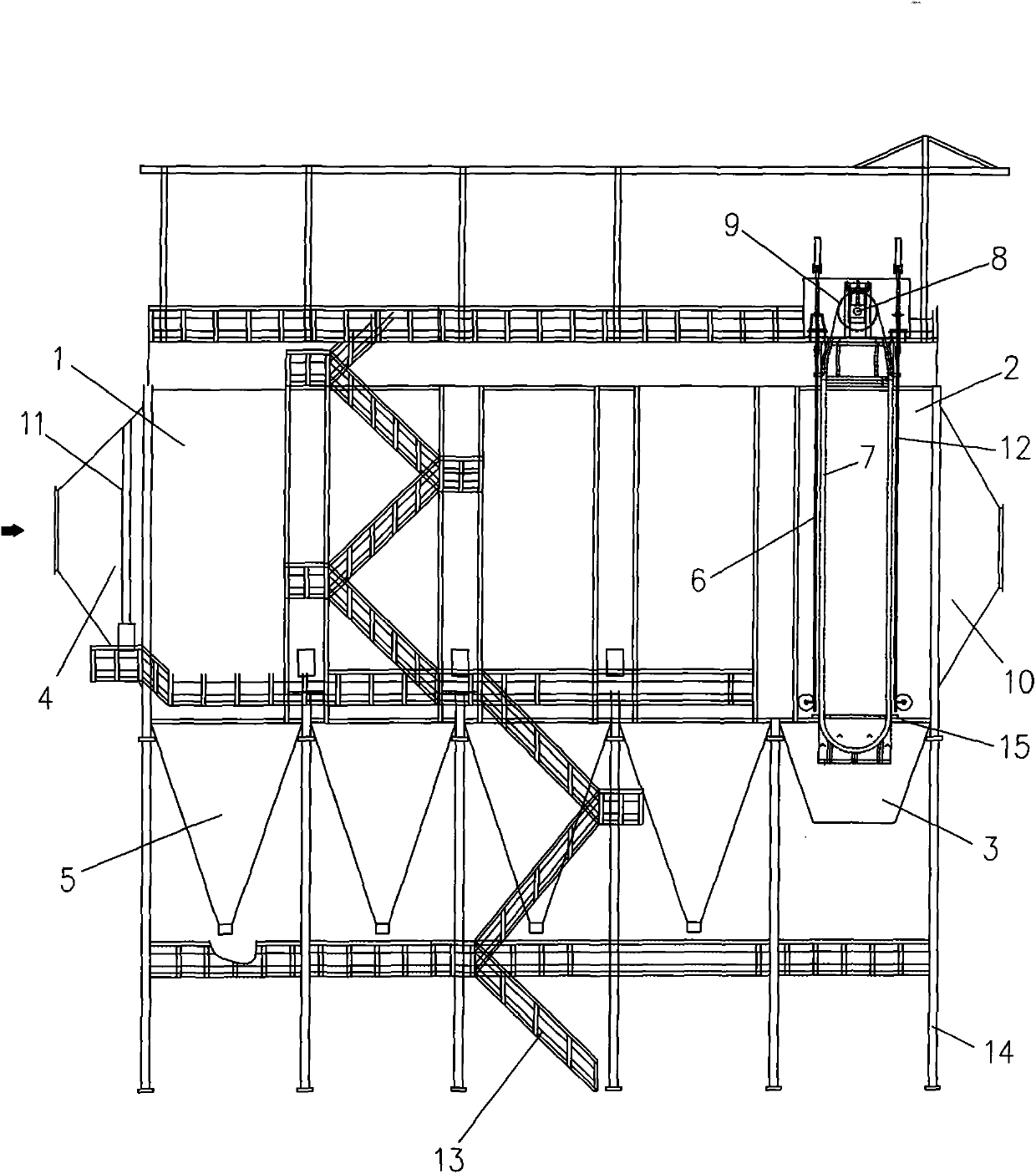
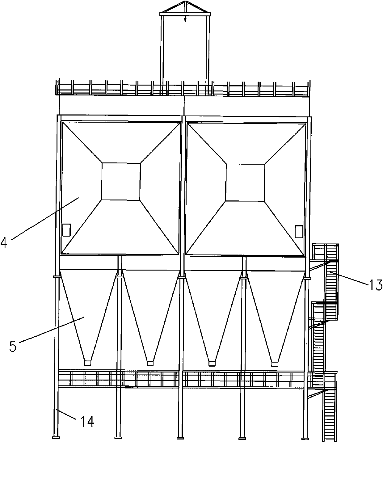
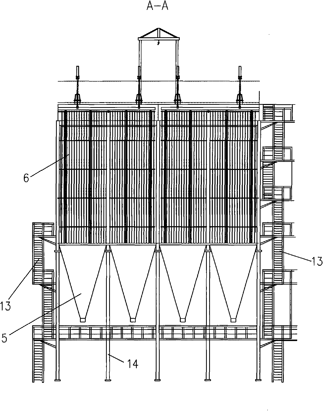
[0025] Such as figure 1 , figure 2 with image 3 As shown, the combined radial flow electrostatic precipitator of the present invention includes a housing 1. The housing 1 is provided with a dust removal air passage 2 along the front and rear directions, and the front of the housing 1 is provided with an air inlet for the dust removal air passage 2. The rear of the shell 1 is provided with an exhaust port for the dust removal air duct 2. The dust removal air duct 2 is equipped with a discharge electrode (not shown in the figure) that can charge the dust particles in the air and a collector for adsorbing dust particles. Dust electrode (not shown in the figure), below the dust collecting electrode is equipped with a ash hopper 5 for collecting dust falling from the dust collecting electrode, and the dust removal air duct 2 is located behind the dust collecting electrode with a radial electric dust removal discharge Net 6, the net surface of the radial electric precipitating and d...


PUM

PropertyMeasurementUnit
Bulk densityaaaaaaaaaa
Thicknessaaaaaaaaaa
Bulk densityaaaaaaaaaa

Abstract

The invention discloses a combined type radial current electric dust collector. According to the dust collector, a radial current type electric dust collecting power discharge net is arranged behind a dust collecting electrode inside a dust collecting airway; an annular dust collecting chain row is arranged behind the radial current type electric dust collecting power discharge net; the front annular part of the dust collecting chain row is parallel to the surface of the radial current type electric dust collecting power discharge net; a left guide rail is arranged on the left side of the dust collecting chain row; the side part of the left end of the dust collecting chain row is guided and positioned through the left guide rail; a right guide rail is arranged on the right side of the dust collecting chain row; the side part of the right end of the dust collecting chain row is guided and positioned through a right guide rail; the lower part of the dust collecting chain row is positioned inside a dust cleaning chamber; a sealing partitioning plate is arranged between the dust cleaning chamber and the dust collecting airway; the dust collecting chain row penetrates through the sealing partitioning plate downwards and enters the dust cleaning chamber; a dust blowing tube is arranged along the left and right direction near the dust collecting chain row inside the dust cleaning chamber. The invention aims at providing the combined type radial current electric dust collector which is large in gas treatment capability in unit time, outstanding in effect in collecting fine dust including PM2.5, very stable in dust collection performance, low in operation cost and long in service life.

Description

Technical field [0001] The invention relates to a combined radial flow electrostatic precipitator. Background technique [0002] PM2.5 refers to particulate matter with a diameter of less than or equal to 2.5 microns in the atmosphere, and is also called lung particulate matter. Although PM2.5 is only a small component in the earth's atmosphere, it has an important impact on air quality and visibility. PM2.5 has a small particle size, is rich in a large amount of toxic and harmful substances, has a long residence time in the atmosphere and a long transportation distance, so it has a greater impact on human health and atmospheric environmental quality. Meteorological experts and medical experts believe that the haze caused by fine particles is even more harmful to human health than sandstorms. Particles with a particle size of 10 microns or more will be blocked from the outside of the human nose; particles with a particle size between 2.5 microns and 10 microns can enter the upp...

Claims


Application Information

Patent Timeline
IPC IPC(8): B03C3/47B03C3/41B03C3/80B03C3/34B03C3/60
Inventor 孟金来
Owner 北京华能达电力技术应用有限责任公司
Why Eureka
Try Eureka