Gantry type multiple-spindle machining center

A processing center and gantry-type technology, applied in metal processing equipment, metal processing machinery parts, manufacturing tools, etc., can solve problems such as restricting productivity, affecting processing efficiency, and increasing machine assistance, so as to enhance equipment strength and reduce loading and unloading time , Improve the effect of machining accuracy

Inactive Publication Date: 2014-04-16
林志贺
View PDF8 Cites 6 Cited by
  • Summary
  • Abstract
  • Description
  • Claims
  • Application Information

AI Technical Summary

Problems solved by technology

[0002] At present, the machining centers on the market are basically single-spindle structures, which are relatively inefficient for large-scale processing of some small and medium-sized parts, because only one tool is involved in processing at the same time.
However, although the combination machine tool can participate in the cutting with multiple spindles at the same time and improve the efficiency, its versatility is poor, and adjustment and maintenance are also troublesome.
A Chinese patent discloses a gantry multi-axis machining center (patent number: 201120550910.9). Although it adopts a multi-spindle structure, its tools cannot be automatically replaced, thereby restricting productivity
At present, some gantry machining centers on the market adopt a double-spindle structure, but they cannot perform simultaneous tool changes on the two spindles, which affects the processing efficiency.
In addition, in the machining of large batches of parts, the loading and unloading time of many parts accounts for a large share of the total time. In addition, the untimely nature of employees in loading and unloading has greatly increased machine assistance, which has affected production efficiency.

Method used


Image

  • Gantry type multiple-spindle machining center
  • Gantry type multiple-spindle machining center
  • Gantry type multiple-spindle machining center

Examples


Embodiment 1

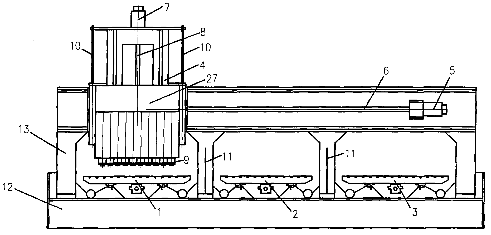
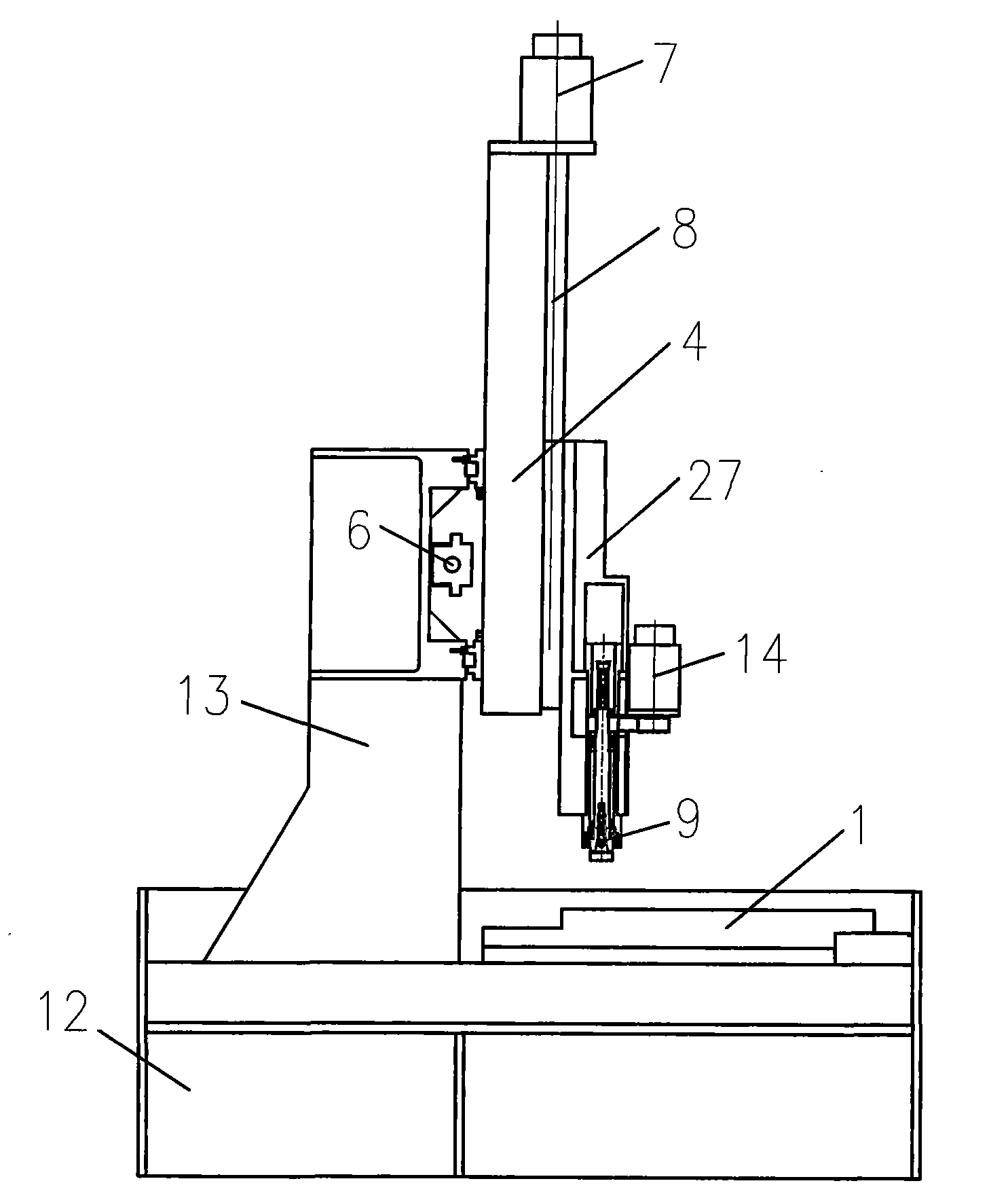
[0016] Embodiment 1: refer to figure 1 , 2 As shown, in this embodiment, the machining center adopts the structure of three gantry parallels; the X-direction sliding table of the base is composed of three independently parallel-installed CNC servo sliding tables, namely, left sliding table 1, middle sliding table 2, and right sliding table 3. Among them, the left sliding table 1 and the right sliding table 3 are used to install the processed parts; the middle sliding table 2 is used to install Figure 4 In-line flush tool changer shown. The Y-direction sliding table 4 on the gantry 13 uses a servo motor 5 and a ball screw 6 to drive it to walk among the three X-direction sliding tables 1, 2, and 3; its Z-direction sliding table 27 uses a No. 2 servo motor 7 The No. 2 rolling screw 8 drives a BT30 machining center spindle unit 9 with 10 tool changers, and the 10 spindle units 9 are arranged equidistantly; the sliding table plate of the Z-direction sliding table 27 is connecte...

Embodiment 2

[0019] Embodiment 2: refer to Figure 5 As shown, the machining center in this embodiment adopts the structure of 4 gantry parallels; the X-direction sliding table of the base is composed of No. 1 sliding table 15, No. 2 sliding table 16, No. 3 sliding table 17, and No. 4 sliding table 18. No. 2 sliding table 16 and No. 3 sliding table 17 are used to install workpieces, and are driven by independent CNC servos; No. 1 sliding table 15 is used to install tool magazines, and the tools of this tool magazine are used to process the products of No. 2 sliding table 16 Use, its displacement transmission fixes No. 1 sliding table 15 and No. 2 sliding table 16 sliding table plates together through No. 1 connecting plate 19, thereby realizing synchronous displacement; Can reduce cost like this, and simplify control system. The No. 4 sliding table 18 is also used to install the tool magazine. The tools of the tool magazine are used to process the products of the No. 3 sliding table 17. It...

Embodiment 3

[0021] Embodiment 3: refer to Figure 6 As shown, the machining center in this embodiment adopts the structure of parallel 2 gantry; the X-direction sliding table of its base is composed of left sliding table 21 and right sliding table 22, and are respectively driven by independent numerical control servo; left sliding table 21 and right sliding table The front part of platform 22 is all used for installing workpiece, and the rear part is all used for installing tool magazine. Its Y direction slide table and Z direction slide table structure are identical with the first embodiment.

[0022] The difference between the third embodiment and the first and second embodiments is that in the third embodiment, the workpiece and the tool magazine are installed on the same sliding table, which simplifies the structure, but the stroke of the X-axis sliding table is also compared with the first and the first. The length of the second embodiment.

[0023] In the above-mentioned embodimen...


PUM


Abstract

The invention relates to a gantry type multiple-spindle machining center. A gantry type machining center frame is adopted for the machining center body. The gantry type multiple-spindle machining center is characterized in that X-direction sliding tables of a base of the machining center are formed by installing a plurality of numerical control servo sliding tables in parallel, and at least two sliding tables are used for installing parts to be machined; Y-direction sliding tables on a gantry can be moved between the several X-direction sliding tables in a numerical control servo mode according to the travel; Z-direction sliding tables are installed on the Y-direction sliding tables, and a plurality of spindles with automatic tool changing mechanisms are installed on sliding plates of the Z-direction sliding tables; a horizontally arranged tool magazine is adopted as the tool magazine for automatic tool changing. Machining can be carried out by the machining center through the multiple spindles at the same time, tools can be changed automatically and synchronously, workpieces can be loaded and unloaded in the machining process, and the production efficiency is high. The gantry type multiple-spindle machining center is widely applicable to mechanical cutting of medium and small parts.

Description

technical field [0001] The invention relates to a machining equipment, in particular to a multi-spindle machining center. technical background [0002] At present, the machining centers on the market are basically single-spindle structures, which are relatively inefficient for mass processing of some small and medium-sized parts, because only one tool is involved in processing at the same time. However, although multi-spindle machine tools can participate in cutting at the same time to improve efficiency, the combination machine tool has poor versatility and is troublesome to adjust and maintain. A Chinese patent discloses a gantry multi-axis machining center (patent number: 201120550910.9). Although it adopts a multi-spindle structure, its tools cannot be automatically replaced, thereby restricting productivity. At present, there are also some gantry machining centers on the market that adopt a dual-spindle structure, but they cannot perform synchronous tool changes on the...

Claims


Application Information

Patent Timeline
Patent Type & Authority Applications(China)
IPC IPC(8): B23P23/00B23Q3/157B23Q1/64
CPCB23Q3/15786B23Q1/64
Inventor 林志贺
Owner 林志贺
Why Eureka
Try Eureka