
Electric hair trimmer

A hair clipper and electric technology, applied in metal processing and other directions, can solve the problems of unusable cutter head components, decreased sharpness, increased noise, etc., and achieve the effects of improving haircut efficiency, reducing friction, and reducing load current

Active Publication Date: 2014-04-16
HUANXING TECH HANGZHOU CO LTD
View PDF9 Cites 4 Cited by
  • Summary
  • Abstract
  • Description
  • Claims
  • Application Information

AI Technical Summary

Problems solved by technology

And because the cutter head assembly cannot continue to be used, most consumers will choose to buy new hair clippers, which undoubtedly causes great waste
[0006] In response to the above problems, some manufacturers will give consumers a cutter head with the machine to facilitate consumers to replace and use, but this method does not effectively solve the above problems, and the gift cutter head will still exist after a period of time Issues with reduced sharpness and increased noise, which eventually rendered the cutter head assembly unusable

Method used


Image

  • Electric hair trimmer
  • Electric hair trimmer
  • Electric hair trimmer

Examples


Embodiment 1

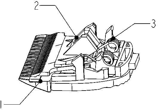
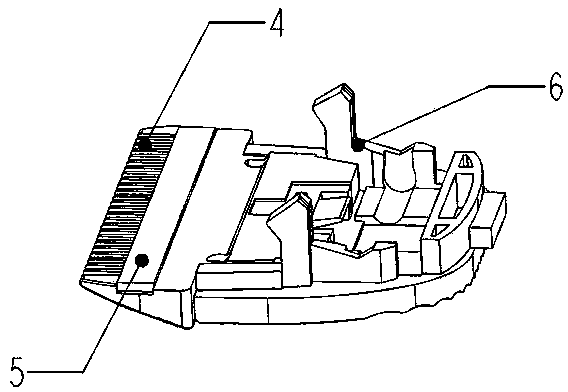
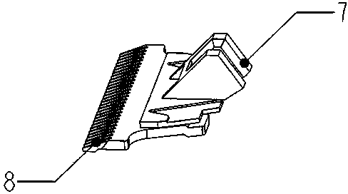
[0030] see Figure 1~7 As shown, an electric hair clipper includes a cutter head assembly, a motor, a rotating shaft and a power supply. The cutter head assembly includes a fixed knife assembly 1, a moving knife assembly 2 and a fine-tuning mechanism 3, and the moving knife assembly is arranged above the fixed knife assembly. The moving knife assembly includes a fixedly connected moving knife 8 and a moving knife driving frame 7; the fine-tuning mechanism includes an adjustment block 9 and a torsion spring 10 arranged on the adjustment block; the two ends of the torsion spring are plugged into the On the driving frame of the moving knife, the moving knife has the freedom of movement of swinging left and right and sliding back and forth relative to the fixed knife assembly; the upper surface of the fixed knife assembly is provided with a grinding bar 5.

[0031] The fixed knife assembly includes a fixed frame 6 and a fixed knife 4 fixedly connected; the fixed knife is provided ...

Embodiment 2

[0038] see Figure 8 As shown, an electric hair clipper includes a cutter head assembly, a motor, a rotating shaft and a power supply, the cutter head assembly includes a fixed knife assembly, a moving knife assembly and a fine-tuning mechanism, and the moving knife assembly is arranged above the fixed knife assembly; The movable knife assembly includes a fixedly connected movable knife and a movable knife drive frame; the fine-tuning mechanism includes an adjustment block and a torsion spring arranged on the adjustment block; the two ends of the torsion spring are plugged into the movable knife drive frame, The movable knife has the freedom of swinging left and right and sliding back and forth relative to the fixed knife assembly; the upper surface of the fixed knife assembly is provided with a grinding layer.


PUM


Abstract

The invention discloses an electric hair trimmer comprising a cutter head unit, a motor, a rotating shaft, and a power source. The cutter head unit comprises a fixed cutter unit, a moving cutter unit and a fine adjustment mechanism. The moving cutter unit is arranged above the fixed cutter unit. The moving cutter unit comprises a moving cutter and a moving cutter drive rack. The fine adjustment mechanism comprises an adjusting block and a torsion spring arranged on the same. Two ends of the torsion spring are inserted onto the moving cutter drive rack, so that the moving cutter has a degree of freedom of motion, rocking left and right and sliding back and forth relative to the fixed cutter unit. The upper surface of the fixed cutter unit is provided with a grinding bar or a grinding layer. The grinding bar or grinding layer is disposed on the upper surface of the fixed cutter unit, so that the trimmer has the function of blade sharpening; when the shearing sharpness of the cutter head decreases, the cutter head can be ground with the grinding bar or grinding layer and kept sharp, hair-cutting efficiency is improved, the service life of the cutter head is greatly prolonged, and cost is saved.

Description

technical field [0001] The invention relates to an electric hair clipper. Background technique [0002] In modern families, haircuts are already synonymous with fashion. Usually, in the public perception, haircuts need to go to barbershops, while in foreign countries, consumers not only go to barbershops for haircuts, but also buy a family Hair clippers to cut hair for your family. With the gradual improvement of domestic consumption level, more and more families realize that haircutting at home is a healthy and fashionable way of life. The consumption concept has gradually changed from paying attention to fashion to focusing on health. Buying a family-specific hair clipper has become It has become one of the necessary standard configurations for many emerging home care appliances. [0003] At the same time, in the hairdressing industry, electric hair clippers are also one of the essential supplies for barber shops. [0004] Existing hair clipper mainly contains two kinds...

Claims


Application Information

Patent Timeline
Patent Type & Authority Applications(China)
IPC IPC(8): B26B19/04
Inventor 吴景郭斌
Owner HUANXING TECH HANGZHOU CO LTD
Learn More