Non-return quantitative constant-pressure injection device

An injection device and non-return technology, which is applied in the field of non-return quantitative and constant pressure injection devices, can solve problems such as large resistance, curved flow channels, and complexity, and achieve the effects of simplified product structure, high reliability, and quantitative injection

Active Publication Date: 2014-04-16
佛山市韵雄塑料五金制品有限公司
View PDF11 Cites 18 Cited by
  • Summary
  • Abstract
  • Description
  • Claims
  • Application Information

AI Technical Summary

Problems solved by technology

But this check valve also has the following problems that cannot be solved. 1. When the liquid needs to be completely sealed, this water-saving check valve cannot realize this function; Reduce the water flow area to achieve water-saving function. When the use environment is such as high liqui

Method used


Image

  • Non-return quantitative constant-pressure injection device

Examples


Embodiment Construction

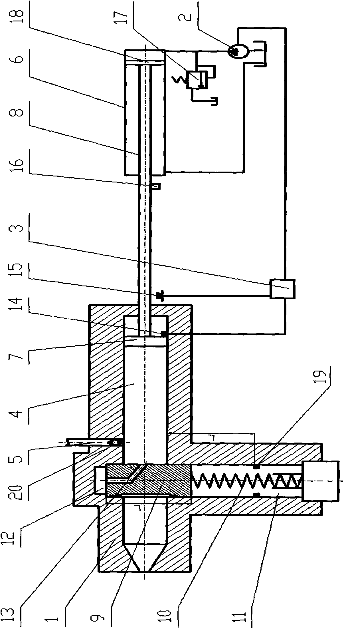
[0015] The present invention will be further described below in conjunction with the accompanying drawings and specific embodiments.

[0016] Such as figure 1 As shown, the non-return quantitative and constant pressure injection device of the present invention includes a nozzle body 1, a valve core mechanism, an injection cylinder, a hydraulic system 2 and a controller 3, and the nozzle body 1 is provided with a flow channel 4 and a liquid inlet 5. The spool mechanism used to open or close the nozzle body 1 is installed in the nozzle body 1. The injection cylinder includes a cylinder body 6 and a hydraulic rod 8 with a first piston 7 at the front end. A hydraulic rod 8 of a piston 7 extends into the flow channel 4 of the nozzle body 1, the hydraulic system 2 is connected with the cylinder body 6 for driving the injection cylinder, and the injection device also includes a stroke control device for the hydraulic rod. Both the hydraulic system 2 and the stroke control device of ...


PUM


Abstract

The invention discloses a non-return quantitative constant-pressure injection device which comprises a nozzle body, a valve core mechanism, an injection oil cylinder, a hydraulic system and a controller, wherein a flow channel and a liquid inlet are formed in the nozzle body; the valve core mechanism for opening or closing the nozzle body is mounted in the nozzle body; the injection oil cylinder comprises an oil cylinder body and a hydraulic rod with a first piston at the front end part; the hydraulic rod with the first piston extends into the flow channel of the nozzle body; the hydraulic system is connected with the oil cylinder body and is used for driving the injection oil cylinder. The injection device is characterized by further comprising a hydraulic rod stroke control device; both the hydraulic system and the hydraulic rod stroke control device are electrically connected with the controller. The injection device is simple in structure and high in reliability, and can achieve intermittent, quantitative and constant-pressure injection.

Description

technical field [0001] The invention relates to the field of injection devices, in particular to a non-reverse quantitative and constant pressure injection device. Background technique [0002] The injection device is used for fluid injection and is suitable for many occasions, such as high-pressure injection in the hydraulic field, quantitative injection in chemical production, and so on. In the prior art, injection devices often use timing injection to perform injection. At this time, to achieve quantitative injection, it is necessary to ensure uniform feeding (ie, quantitative feeding under one cycle). However, in many cases, it is impossible to maintain uniform feeding or the feeding time is uncertain, resulting in different injection volumes each time, that is, quantitative injection cannot be achieved. Therefore, as a technical index and requirement, quantitative injection needs complicated mechanisms to realize in the prior art. [0003] For example, Chinese patent ...

Claims


Application Information

Patent Timeline
IPC IPC(8): B29C45/53B29C45/23B29C45/20B29C45/77
CPCB29C45/231B29C45/53B29C45/76B29C45/77B29C2945/76498B29C2945/76591B29C2945/76688
Inventor 饶宾期姜源周玲
Owner 佛山市韵雄塑料五金制品有限公司
Why Eureka
Try Eureka