Plastic composite pipe end sealing device of steel skeleton
A technology for end sealing and composite pipes, which is applied in the field of end sealing devices for steel skeleton plastic composite pipes, can solve problems such as complicated pasting process and increased production costs, and achieve good sealing effects, reduced production costs, and improved production efficiency
- Summary
- Abstract
- Description
- Claims
- Application Information
AI Technical Summary
Problems solved by technology
Method used
Image
Examples
Embodiment 1
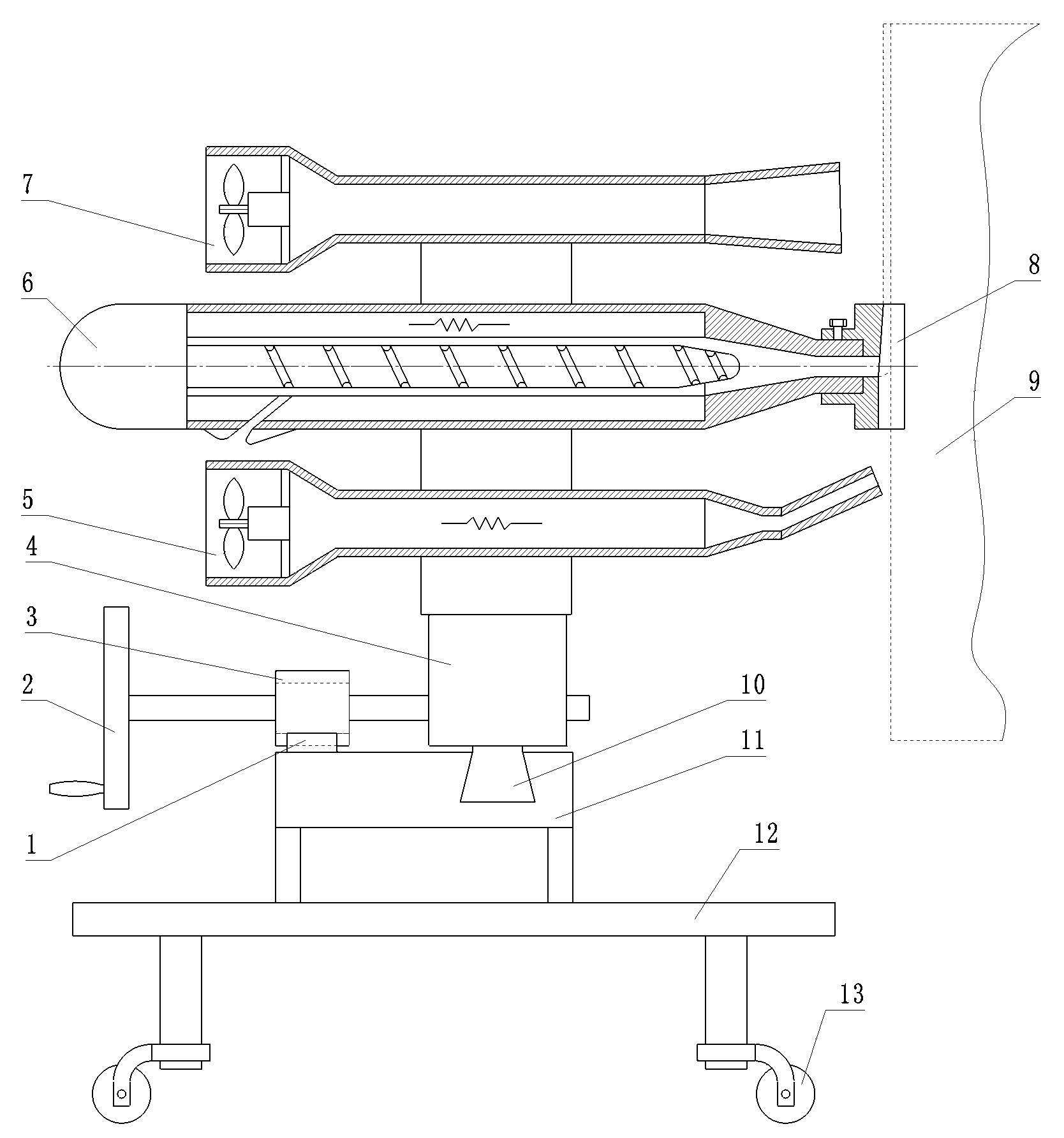
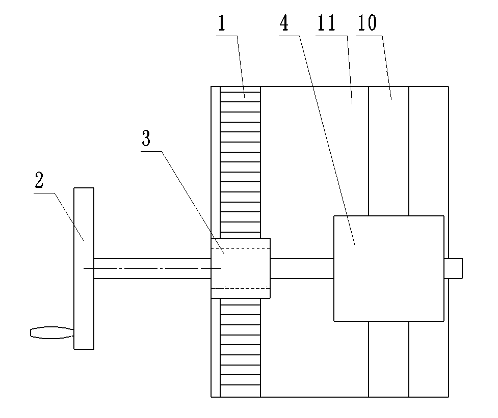
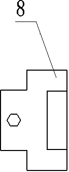
[0024] Example 1 : Refer to attached Figure 1-4 , is a structural schematic diagram of Embodiment 1 of the present invention, including a car body 12, on which wheels 13 are arranged, and the wheels 13 are universal wheels, and a platform 11 is provided on the car body 12, and the hot extrusion Plastic gun 6 and heat gun 5 are installed on the platform 11, are provided with cooling air gun 7 behind the hot extrusion gun 6, so that the limit of the pipe 9 of sealing is cooled as soon as possible, the plastic outlet place of hot extrusion gun 6 is provided with bar The shaping die 8 of the shaped groove, the bottom edge of the rear end of the plastic outlet of the strip groove of the shaping die 8 has an included angle with the vertical direction, that is, there is an included angle with the end face of the pipe, and the strip groove at the rear end of the plastic outlet is in the shape of a large inlet and a large outlet. small trumpet. Hot extrusion gun 6 and hot air gun 5...
Embodiment 2
[0025] Example 2 : Refer to attached Figure 5-6 , is a structural schematic diagram of Embodiment 2 of the present invention. Compared with Embodiment 1, the difference of this embodiment is that the wheels 13 on the car body are rail wheels, which can travel on a track during work, and the car body 12 Also be provided with trimming mechanism 14, trimming mechanism 14 is made up of motor and emery wheel, and the wheel surface of described emery wheel is provided with the groove that section is trapezoidal, can grind the end face of pipe 9 after sealing and repair out. Angle, be provided with cooling air gun 7 between edge mechanism 14 and hot extrusion gun 6. Trimming mechanism 14 is also provided with fine-tuning mechanism simultaneously, and this fine-tuning mechanism comprises chute and slide block, and described trimming mechanism is arranged on the slide block, is provided with displacement propelling mechanism between chute and slide block, and described displacement ...
Embodiment 3
[0026] Example 3 : Refer to attached Figure 7 , is a schematic structural diagram of Embodiment 3 of the present invention. Compared with the previous embodiments, the difference of this embodiment is that the moving and pushing mechanism is a combination of a nut 16 and a screw 15 .
PUM
 Abstract
Description
Claims
Application Information
 - R&D
- Intellectual Property
- Life Sciences
- Materials
- Tech Scout
- Unparalleled Data Quality
- Higher Quality Content
- 60% Fewer Hallucinations
Browse by: Latest US Patents, China's latest patents, Technical Efficacy Thesaurus, Application Domain, Technology Topic, Popular Technical Reports.
© 2025 PatSnap. All rights reserved.Legal|Privacy policy|Modern Slavery Act Transparency Statement|Sitemap|About US| Contact US: help@patsnap.com


