Yarn tension control mechanism of warp knitting machine

A yarn tension and control mechanism technology, applied in warp knitting, textiles, papermaking, knitting, etc., can solve the problems of time error, easy heating, long installation and debugging time, etc.

Active Publication Date: 2014-04-16
FUJIAN XIN GANG TEXTILE MACHINERY
View PDF11 Cites 7 Cited by
  • Summary
  • Abstract
  • Description
  • Claims
  • Application Information

AI Technical Summary

Problems solved by technology

The swing of the tension rod is controlled by the main shaft and transmitted through the synchronous wheel, synchronous belt, eccentric shaft, connecting mechanism, tension spring and sprocket. The accumulation of this process will cause time errors and affect the accuracy and accuracy of yarn feeding. Evenness
Furthermore, the synchronous belt, the synchronous wheel, and the bearings in the eccentric wheel are prone to heat and wear under high-speed operation, and need to be constantly stopped for replacement, which affects the warp knitting efficiency.
And the whole assembly is cumbersome and complicated, the installation and debugging time is long, and the warp knitting cost is high

Method used


Image

  • Yarn tension control mechanism of warp knitting machine
  • Yarn tension control mechanism of warp knitting machine
  • Yarn tension control mechanism of warp knitting machine

Examples


Embodiment Construction

[0011] In order to better understand the present invention, the present invention will be further described in detail with reference to the accompanying drawings.

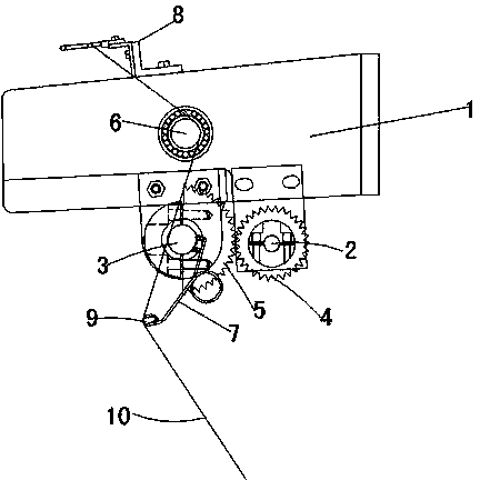
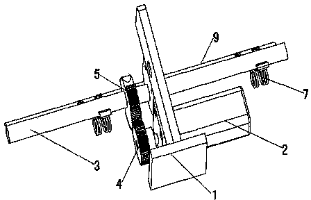
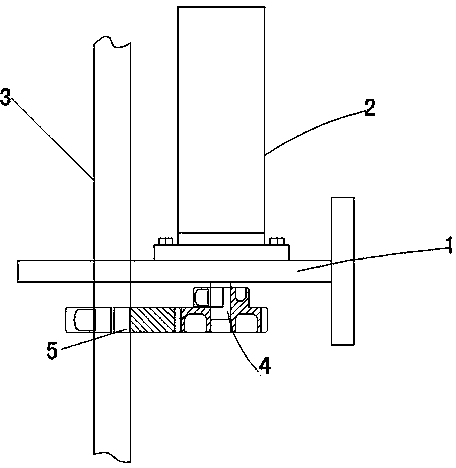
[0012] See Figure 1 to Figure 3 Shown: a yarn tension control mechanism of warp knitting machine, including tension seat (1), tension rod (3), tension spring (7), yarn guide cap (9), yarn passing rod (6), driving gear ( 4), driven gear (5), servo motor (2) and yarn splitting seat (8). The tension seat (1) is fixedly installed on the main beam of the warp knitting machine by bolts, and the tension seat (1) is provided with holes for installing the tension rod (3), the yarn passing rod (6) and the servo motor (2). The tension rod (3) is installed on the tension seat (1), and the passive gear (5) is installed on the tension rod (3). The passive gear (5) is a detachable semicircular gear, so that, The driven gear (5) can be conveniently installed on the tension rod (3) through bolts according to the needs of installati...


PUM


Abstract

The invention discloses a yarn tension control mechanism of a warp knitting machine, which comprises a tension seat, a tension rod, a yarn-through rod, a driving gear, a driven gear and a servo motor, wherein the tension rod and the yarn-through rod are mounted on the tension seat; the driven gear is mounted on the tension rod; tension springs of certain number are equidistantly mounted in the same direction on the tension rod; yarn guide caps are clamped by the tail-end openings of the tension springs; a flange of the servo motor is fixed on the tension seat through a bolt; the driving gear is arranged on an output shaft of the servo motor; the driving gear is meshed with the driven gear; when the servo motor rotates back and forth under the control of the set program, the driving gear rotates along with the servo motor and the driven gear is driven to rotate; the rotation of the driven gear drives the tension rod and the yarn guide caps of the tension springs to rotate; and the control program controls the motor to rotate back and forth according to the rotation speed of a main shaft of the wrap knitting machine to cooperate with the looping motion of the warp knitting machine so as to control the tightness of the yarn tension. The uniformity of the yarn tension is guaranteed, thus the knitting of the warp knitting machine is smooth, the quality of the grey cloth is good, and the production efficiency is high.

Description

Technical field [0001] The invention relates to the field of textile equipment, in particular to a yarn tension control mechanism of a warp knitting machine. Background technique [0002] When the warp knitting machine is in normal operation, the yarn is unwound from the pan head and fed into the loop-forming system according to a certain amount of warp let-off is called let-off mechanism. Under the condition of ensuring normal loop formation, the let-off amount should always be kept accurate and constant, and the yarn-feeding tension should be uniform. Too high average tension and peak tension not only affect the smooth progress of the warp knitting machine weaving process, but also hinder the appearance of the fabric; if the average tension is too low, the minimum tension will be too low, causing the yarn to slack, making the yarn unable to cling to the loop forming machine Complete precise looping movement. [0003] The existing warp knitting machine for tension adjustment and...

Claims


Application Information

Patent Timeline
Patent Type & Authority Applications(China)
IPC IPC(8): D04B27/14
Inventor 郑依福郑春乐赖秋玉
Owner FUJIAN XIN GANG TEXTILE MACHINERY
Why Eureka
Try Eureka