
A prefabricated reinforced concrete slab tire form and its construction method

A reinforced concrete and construction method technology, applied in artificial islands, water conservancy projects, infrastructure projects, etc., can solve the problems of increasing construction procedures, unfavorable guarantee construction period, and prolonging construction time, so as to save labor, shorten construction period, and save The effect of manpower and material resources

Active Publication Date: 2015-12-30
赵群化
View PDF7 Cites 0 Cited by
  • Summary
  • Abstract
  • Description
  • Claims
  • Application Information

AI Technical Summary

Problems solved by technology

[0002] At present, in the construction industry, during the construction of traditional building foundations, the side forms such as foundation beams, independent caps, and sumps are not easy to remove. Generally, the soil is excavated separately, and brick tire molds are often used, that is, masonry brick tire molds. As a formwork; the brick tire formwork requires construction workers to build bricks in the foundation pit, so a large construction space is required, which requires a larger area to be excavated when excavating the foundation pit. After the brick tire formwork construction is completed, the brick A dog’s space is formed between the tire mold and the wall of the foundation pit, and a large amount of soil needs to be backfilled, which wastes manpower and material resources, increases the construction process, and prolongs the construction time. More manpower is invested, the cost is higher, the environment is easily polluted, the construction speed is slow and it is not conducive to ensuring the construction period

Method used


Image

  • A prefabricated reinforced concrete slab tire form and its construction method
  • A prefabricated reinforced concrete slab tire form and its construction method
  • A prefabricated reinforced concrete slab tire form and its construction method

Examples


Embodiment Construction

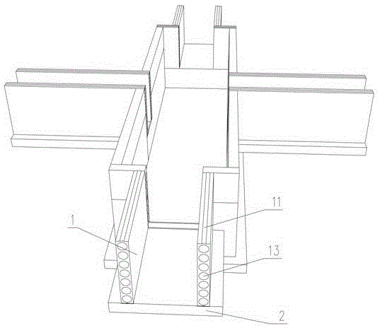
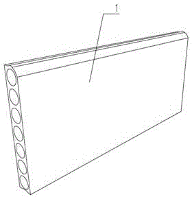
[0032] With reference to the above drawings, a prefabricated reinforced concrete slab tire mold includes a template plate body 1, the template plate body (1) has bosses on the upper surface and grooves on the lower surface, and is characterized in that the template plate body 1 is Rectangular prefabricated reinforced concrete formwork board structure. The upper surface of the formwork board body 1 is provided with a transverse arc-shaped boss 11, and the lower surface is provided with a transverse arc-shaped groove 12 that matches the transverse arc-shaped boss 11, that is, the template board. The upper surface of the body and the lower surface of the template board are superimposed and connected to form an arc-shaped concave-convex matching structure; this arc-shaped concave-convex matching structure prevents damage to the waterproof layer by the square concave-convex matching structure; the side of the template board 1 is provided with uniformly distributed Horizontal through ...


PUM


Abstract

The invention relates to a prefabricated reinforced concrete board molding bed and a construction method which replace frequently-used brick molding beds. According to the board molding bed, a prefabricated reinforced concrete shuttering body is mounted on an in-pit foundation bed through a connecting piece and a fastening piece in an enclosing mode, the shuttering body is of a rectangular prefabricated reinforced concrete shuttering body structure, a horizontal arc-shaped boss used for increasing height is arranged on the upper surface of the shuttering body, a horizontal arc-shaped groove used for increasing height and matched with the horizontal arc-shaped boss is formed in the lower surface of the shuttering body, namely the upper surface and the lower surface of the shuttering body are of a concave-convex matching structure, and evenly distributed horizontal through holes used for containing reinforced concrete sleeves are formed in the lateral sides of the shuttering body. The molding bed made of boards is simple in structure, easy and fast to install, fast in progress and high in quality. Installation is achieved on site in a one-shot mode. The boards can be cut, bricklaying is omitted, labor is saved, cost is saved, and the construction period is shortened.

Description

Technical field [0001] The invention relates to a prefabricated reinforced concrete slab tire mold and a construction method. It is a brand new concrete slab tire mold and construction method that replaces the current commonly used brick tire mold and construction. Background technique [0002] At present, in the construction industry, during the traditional construction of building foundations, the side molds such as foundation beams, independent caps, and sumps are not easily removed. Generally, the soil is excavated separately. Brick tire molds are often used, that is, brick tire molds. As a template; the brick tire mold requires construction workers to build bricks in the foundation pit, so a larger construction space is required. This requires a larger area to be excavated when the foundation pit is excavated. After the brick tire mold construction is completed, the brick A dog space is formed between the tire mold and the foundation pit wall, and a large amount of soil need...

Claims


Application Information

Patent Timeline
Patent Type & Authority Patents(China)
IPC IPC(8): E02D29/045
Inventor 赵群化黎昌军
Owner 赵群化
Learn More