Scroll compressor with ring pin structure

A technology for scroll compressors and casings, applied in the direction of rotary piston machinery, rotary piston pumps, mechanical equipment, etc., can solve the problems affecting the industrialization process, the lack of structural parameters of scroll compressors, etc., and achieve weight Lightweight, improve fit accuracy and parameter optimization, and reduce raw material costs

Active Publication Date: 2016-07-06
NANJING AOTECAR NEW ENERGY TECH
View PDF6 Cites 0 Cited by
  • Summary
  • Abstract
  • Description
  • Claims
  • Application Information

AI Technical Summary

Problems solved by technology

[0003] The purpose of the present invention is to solve the problem that the scroll compressor with the existing ring pin structure cannot fully exert its proper function due to the lack of reasonable structural parameters, which directly affects the industrialization process. Through a large number of experimental verifications, it provides A scroll compressor with ring pin structure, low noise, long life, safe and reliable

Method used


Image

  • Scroll compressor with ring pin structure
  • Scroll compressor with ring pin structure
  • Scroll compressor with ring pin structure

Examples


Embodiment 1

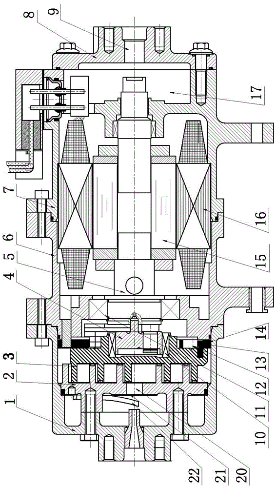
[0028] Such as Figure 1-6 shown.

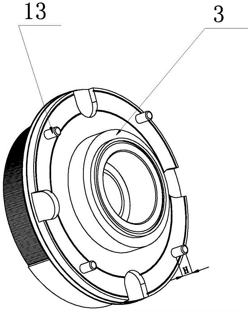
[0029] An electric scroll compressor with ring pin structure, comprising a casing 1, a static disk 2, a moving disk 3, an eccentric sleeve 4, a crankshaft 5, a front cover 6, a motor casing 7 and a rear cover 8, such as figure 1 , 6 As shown, one end of the casing 1 is the exhaust end, and its other end is connected with one end of the front cover 6, and the other end of the front cover 6 is connected with one end of the motor casing 7, and the other end of the motor casing 7 is connected with the rear cover 8 are connected, the rear cover 8 is provided with an air inlet 9, and a motor installation cavity 17 communicating with the air inlet 9 is formed between the front cover 6 and the motor housing 7, and the moving plate 3 and the static plate 2 are inter-inserted and installed in the In the casing 1, one end of the eccentric sleeve 4 is installed on the moving plate 3 through the first bearing 10, and the other end of the eccentric slee...

Embodiment 2

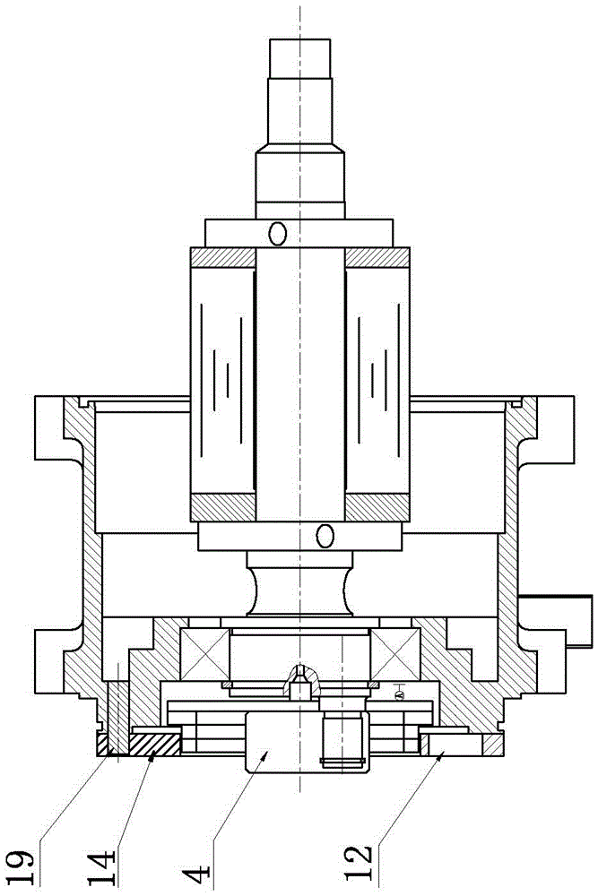
[0033] Such as Figure 7 , 8 shown.

[0034] A scroll compressor with a ring pin structure, including a casing 1, a static disk 2, a moving disk 3, an eccentric sleeve 4, a crankshaft 5, a front cover 6, a motor casing 7 and a rear cover 8, such as Figure 7 , 8 As shown, one end of the casing 1 is the exhaust end, and its other end is connected to one end of the front cover 6, and the other end of the front cover 6 is installed with a driving component, and the moving disk 3 and the static disk 2 are inserted and installed in the casing. 1, one end of the eccentric sleeve 4 is installed on the moving disk 3 through the first bearing 10, the other end of the eccentric sleeve 4 is connected with the crankshaft 5 passing through the front cover 6, and the end of the crankshaft 5 installed with the eccentric sleeve 4 is supported on the second bearing 11, its other end is also supported on the corresponding bearing and a pulley 23 is installed, and four pins 13 (such as figu...


PUM


Abstract

The invention discloses a vortex compressor with a gasket pin structure. The vortex compressor with the gasket pin structure comprises a machine shell (1), a static disk (2), a dynamic disk (3), an eccentric sleeve (4), a crankshaft (5) and a front cover (6), and is characterized in that pins (13) are arranged on the end surface, opposite to the front cover (6), of the dynamic disk (3); a gasket (14) with the thickness of 3 to 5.5 mm, the hardness of HRC 40 to 50, the material of 40Cr or 20CrMo is arranged on the end surface, opposite to the dynamic disk (3), of the front cover (6); circular holes (12) with the same number as that of the pins (13) are formed in the gasket (14); the height H of each pin (13) is equal to 80 to 95 percent of the thickness of the gasket (14); the gasket (14) is positioned on the end surface, opposite to the dynamic disk (3), of the front cover (6) through a positioning pin (19); the positioning pin (19) is in clearance fit with the corresponding positioning hole (14a) in the gasket (14); the fit clearance between the positioning pin (19) and the positioning hole (14a) is 0.045 to 0.127. The vortex compressor with the gasket pin structure has the advantages of simple structure, light weight and convenience in installation.

Description

technical field [0001] The invention relates to a scroll compressor, in particular to a scroll compressor with simple structure and high transmission efficiency, specifically a scroll compressor with ring pin structure. Background technique [0002] As we all know, in scroll compressors (electric or conventional power), in order to make the rotor plate swing in the plane driven by the crankshaft, it is necessary to restrict the rotor disc from rotating. Currently, the commonly used methods include the structure of steel balls plus fixed ball rings and There are two types of ring pin structures. Chinese patents 2006100405145 and 2008100236786 all use the structure of steel balls and fixed bead rings. In order to ensure wear resistance, stop rings need to be installed on the end face and front end surface of the moving disc, and because the steel The volume of the ball is large, which increases the volume and weight of the scroll compressor; in addition, because the fixed bead...

Claims


Application Information

Patent Timeline
Patent Type & Authority Patents(China)
IPC IPC(8): F04C18/02F04C29/06
Inventor 不公告发明人
Owner NANJING AOTECAR NEW ENERGY TECH
Why Eureka
Try Eureka