Preparation method of light guide plate, light guide plate, backlight module and display device

A technology of light guide plate and light emitting surface, which is used in printing devices, light guides, optics, etc., can solve the problems of long contact time between the light guide plate and high-temperature molds, poor yellowing cannot be fundamentally solved, and the chromaticity of the light source has a great influence. Eliminate poor yellowing, improve poor yellowing, and reduce the effect of the preparation process

Inactive Publication Date: 2014-04-16
HEFEI BOE OPTOELECTRONICS TECH +1
View PDF9 Cites 6 Cited by
  • Summary
  • Abstract
  • Description
  • Claims
  • Application Information

AI Technical Summary

Problems solved by technology

At this time, in order to reduce the difficulty of optical design, the short side of the glue is generally used to prepare the light guide plate by injection molding. In the process of automatic molding) the raw material preparation process is longer, the contact time between the light guide plate and the high-temperature mold is longer, and the degree of carbonization of the material is relatively serious compared with the way of long-side glue, so that the light transmission through the carbonized raw material has a negative effect on the chromaticity of the light source greater influence, causing the picture on the side opposite to the light-incident side to turn yellow
[0005] Existing solutions include selecting light guide plate materials with good fluidity, using high-speed injection molding machines, and using diamond dots to make light guide plate mold cores, etc., but these methods can only reduce yellowing to a certain extent, and with the backlight mold The reduction effect of the increase of the group size is limited, and the problem of bad yellowing cannot be fundamentally solved

Method used


Image

  • Preparation method of light guide plate, light guide plate, backlight module and display device
  • Preparation method of light guide plate, light guide plate, backlight module and display device
  • Preparation method of light guide plate, light guide plate, backlight module and display device

Examples


Embodiment

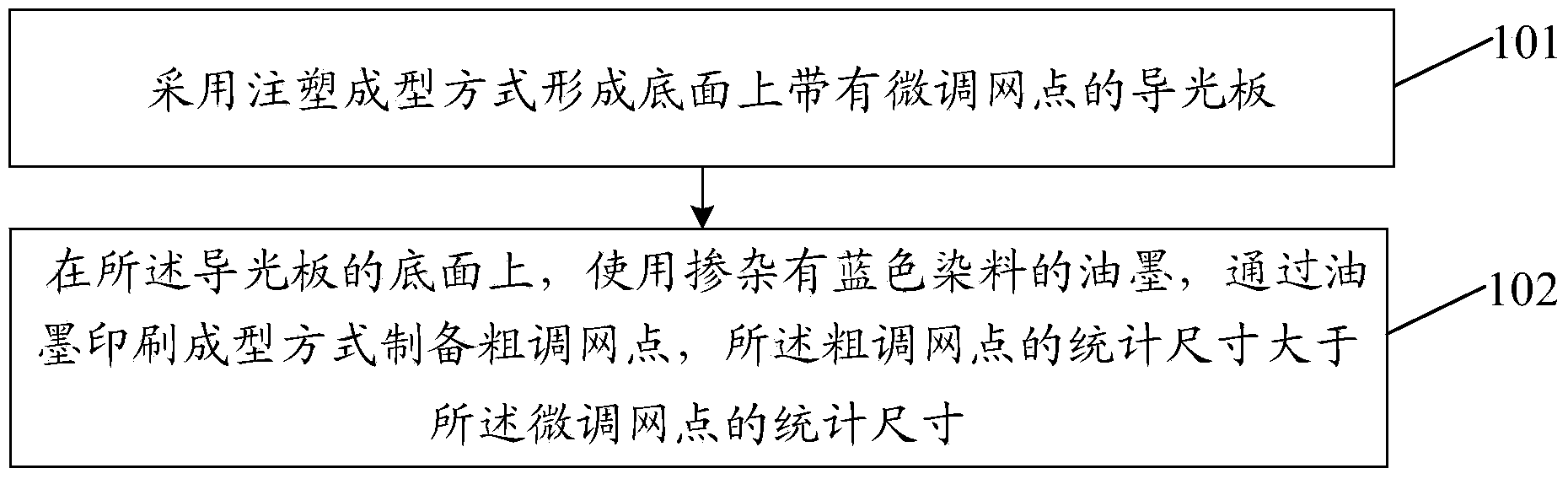
[0027] Embodiments of the present invention provide a method for preparing a light guide plate, such as figure 1 As shown, the method includes:

[0028] 101. A light guide plate with fine-tuning dots on the bottom surface is formed by injection molding, and the bottom surface is opposite to the light-emitting surface of the light guide plate;

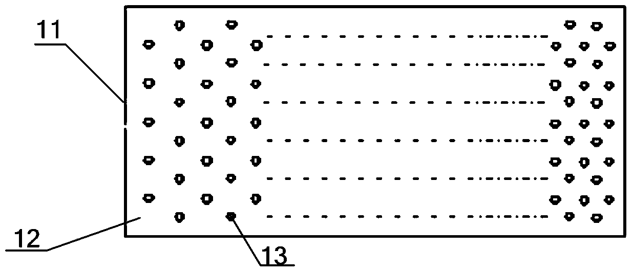
[0029] The dots on the light guide plate are the main factors affecting the light quality, so the dot design is a key point in the design of the backlight module. Dot design means that the designer optimizes the shape, size, distribution density, and distribution rules of the dots on the bottom surface of the light guide plate by using the corresponding dot design software and combining the experience accumulated by the designer, so that the light output of the light guide plate meets the product requirements. The dot design is not the focus of the implementation of the present invention, and is not directly related to the implementati...


PUM


Abstract

The embodiment of the invention discloses a preparation method of a light guide plate, the light guide plate, a backlight module and a display device, and relates to the field of display. The preparation method of the light guide plate, the light guide plate, the backlight module and the display device can effectively improve bad yellowing of a back light source and improve the brightness and evenness of outgoing light of the light guide plate. The preparation method of the light guide plate comprises the steps that the light guide plate with fine adjusting lattice points on the bottom face is formed by adopting an injection molding mode, and the bottom face is opposite to a light outgoing surface of the light guide plate; on the bottom face of the light guide plate, rough adjusting lattice points are prepared through an ink printing forming mode by using ink mingled with blue dyestuff, and the average size of the rough adjusting lattice points is larger than that of the fine adjusting lattice points.

Description

technical field [0001] The invention relates to the display field, in particular to a preparation method of a light guide plate, a light guide plate, a backlight module and a display device. Background technique [0002] The light guide plate is one of the key components of the backlight module. During preparation, an optical-grade acrylic sheet (or other materials) is formed first, and then the light guide point is printed on the bottom surface of the acrylic sheet using ultraviolet screen printing technology. . The light emitted by the light source enters the acrylic plate from the light incident surface and is transmitted therein. When it hits each light guide point, the reflected light will spread to various angles and then be emitted from the light exit surface of the light guide plate. By optimizing the density and size of the light guide points, the light output surface of the light guide plate can obtain high-brightness and uniform luminance output light. [0003] ...

Claims


Application Information

Patent Timeline
Patent Type & Authority Applications(China)
IPC IPC(8): G02B6/00G02F1/13357B29C45/00B41M1/12
Inventor 占江徽吕昶何红超陈守年朴辰武
Owner HEFEI BOE OPTOELECTRONICS TECH
Why Eureka
Try Eureka