Concurrent computation optical bar chart phase extraction method

A phase extraction and parallel computing technology, applied in the direction of using optical devices, multi-channel programming devices, instruments, etc., can solve the problems of long time, increasing the number of wavelet transforms, and slow calculation and processing speed.

Active Publication Date: 2014-04-16
BEIJING GUOWANG OPTICAL TECH CO LTD
View PDF2 Cites 18 Cited by
  • Summary
  • Abstract
  • Description
  • Claims
  • Application Information

AI Technical Summary

Problems solved by technology

However, the essence of wavelet transform is actually convolution and correlation calculation, and the calculation processing speed is relatively slow.
[0004] The wavelet transform optical fringe image processing method in the prior art 3 only uses a serial computing hardware platform, the data processing process follows the ranks, and the multi-scale order is successively cyclically calculated
In addition to the inherently time-consuming convolution calculation of the algorithm itself, there are also the following disadvantages and deficiencies: With the increase of frequency components contained in the image, in order to maintain the calculation accuracy, the number of scale factors selected increases, and the number of scale factors in a single wavelet cycle increases. The number of calculations increases; the increase in the size of the graph will increase the number of wavelet transformations that need to be performed; the serial calculation wavelet transformation optical fringe image processing method takes a long time and cannot meet the needs of real-time measurement

Method used


Image

  • Concurrent computation optical bar chart phase extraction method
  • Concurrent computation optical bar chart phase extraction method
  • Concurrent computation optical bar chart phase extraction method

Examples


Embodiment

[0053] The implementation process is to test the acceleration effect of the parallel computing optical fringe pattern phase extraction method on a multi-core CPU computing platform.

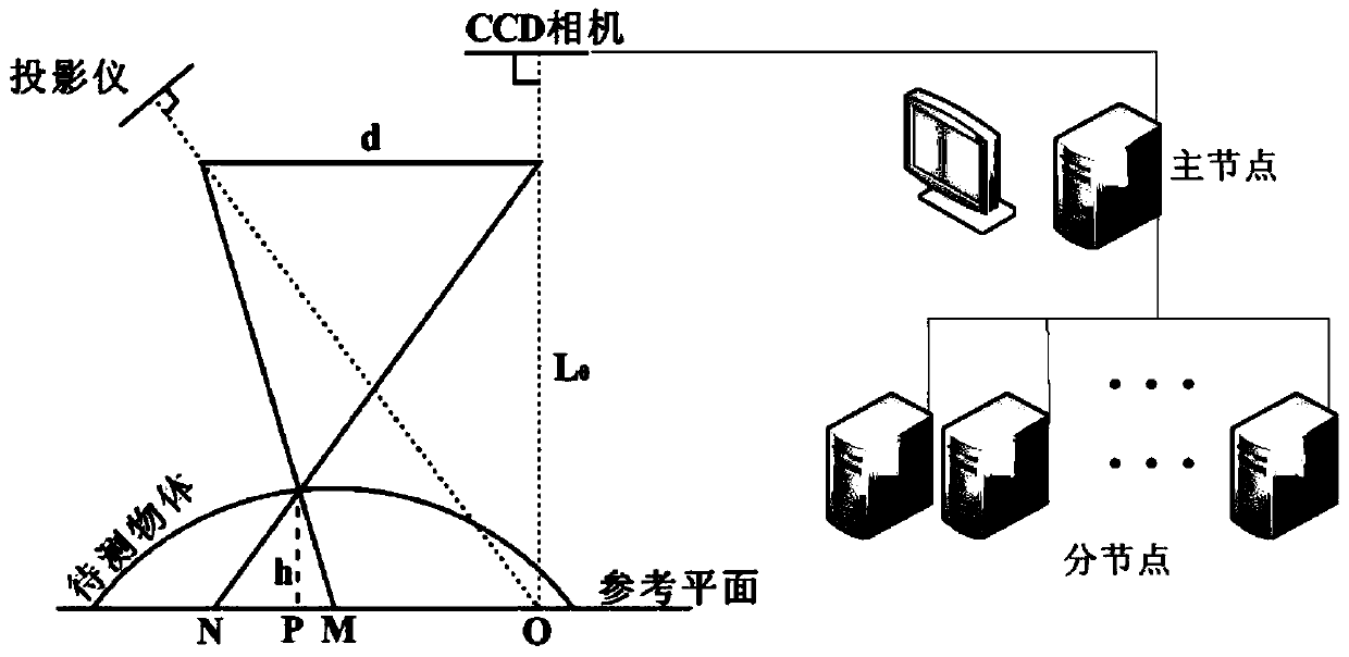
[0054] The optical path of optical fringe pattern measurement in 3D surface inspection is as follows: figure 1 As shown, the projection system projects sinusoidal structure fringes onto the surface of the measured object, and the CCD acquires the optical fringe pattern. The main node CPU reads the image (the optical fringe image to be tested is generated by computer simulation, and the phase generated by the peak function is used to modulate the sinusoidal function to obtain the deformed optical fringe image, and the image size is 1024×1024). The number of scale factors is 40.

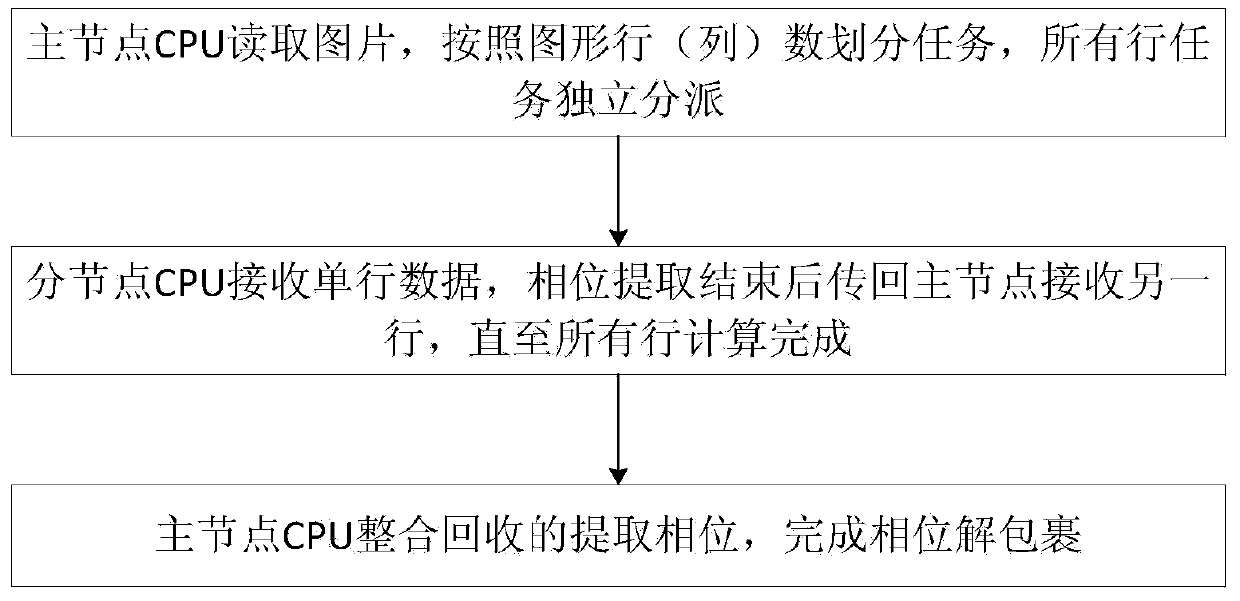
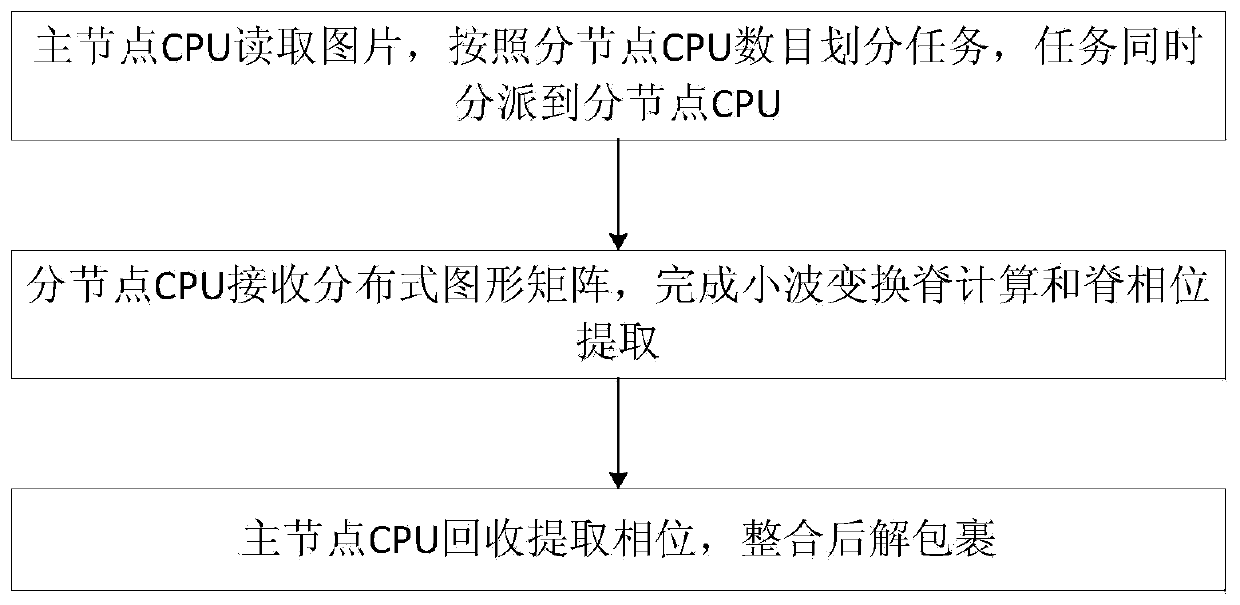
[0055] The processing of wavelet transform on the optical fringe pattern includes the dephase processing of 1024 lines, and the calculation task is 1024 independent cycles. According to the two task scheduling methods d...


PUM


Abstract

A concurrent computation optical bar chart phase extraction method adopts a multi-node CPU computation platform consisting of a multi-core CPU or a computer cluster. A main node CPU finishes image reading and concurrent task partitioning and dispatch. A sub-node CPU processes allocated phase solution tasks and transmits results to the main node CPU. The main node CPU obtains the sub-node computation results and finishes phase unwrapping. The method improves the data processing speed while keeping the accuracy of a serial wavelet transform optical bar chart phase extraction method.

Description

technical field [0001] The invention relates to optical image processing, in particular to a phase extraction method for parallel computing optical fringe images. Background technique [0002] In the structured light projection three-dimensional surface shape measurement technology, the optical fringe pattern carries the three-dimensional surface shape information of the measured object, and the high-precision and fast processing and information acquisition of the optical fringe pattern are the keys to realize the real-time measurement of the three-dimensional surface shape. [0003] Commonly used optical fringe image processing methods include phase shift method (prior technology 1: Zheng Dongliang, Da Feipeng. Two-step phase shift grating projection measurement profilometry. Acta Optics Sinica 2012,32(5):0512004), Fourier transform method (in Prior Technology 2: Zhang Qican, Su Xianyu, Cao Yiping. Using stroboscopic structured light to measure the three-dimensional surface...

Claims


Application Information

Patent Timeline
Patent Type & Authority Applications(China)
IPC IPC(8): G06F9/50G01B11/25
Inventor 余程李思坤王向朝
Owner BEIJING GUOWANG OPTICAL TECH CO LTD
Why Eureka
Try Eureka