Battery coating machine

A coating machine and storage battery technology, applied in the direction of lead-acid battery electrodes, electrode collector coating, electrode manufacturing, etc., can solve the problems of increased production costs, easily damaged coating strips, plate weight and thickness deviation, etc. To achieve the effect of reducing waste and pollution, overcoming easy damage, and improving stability

Active Publication Date: 2016-01-20
中国船舶重工集团衡远科技有限公司
View PDF11 Cites 0 Cited by
  • Summary
  • Abstract
  • Description
  • Claims
  • Application Information

AI Technical Summary

Problems solved by technology

[0002] With the rapid development of the battery industry, the demand for batteries is increasing, and the requirements for reducing the cost of batteries are getting higher and higher. With the emergence of continuous production lines, traditional lead-acid battery coating equipment can no longer meet the requirements. There is an urgent need A high-efficiency, high-precision, low-pollution and easy-to-maintain equipment replaces traditional products
[0003] Existing battery coating machines mostly use the coating belt as the coating working platform. The coating belt is easily damaged and needs to be replaced frequently, which not only affects the coating efficiency of the battery plate, but also increases the production cost. Moreover, the apparent density of the lead paste Larger, if the equipment runs unstable during coating, it will cause large deviations in the weight and thickness of the plates; moreover, the paste speed of the existing battery coating machine is relatively slow, and the amount of paste cannot be effectively controlled, which is extremely It is easy to cause waste and pollution of lead paste

Method used


Image

  • Battery coating machine
  • Battery coating machine
  • Battery coating machine

Examples


Embodiment Construction

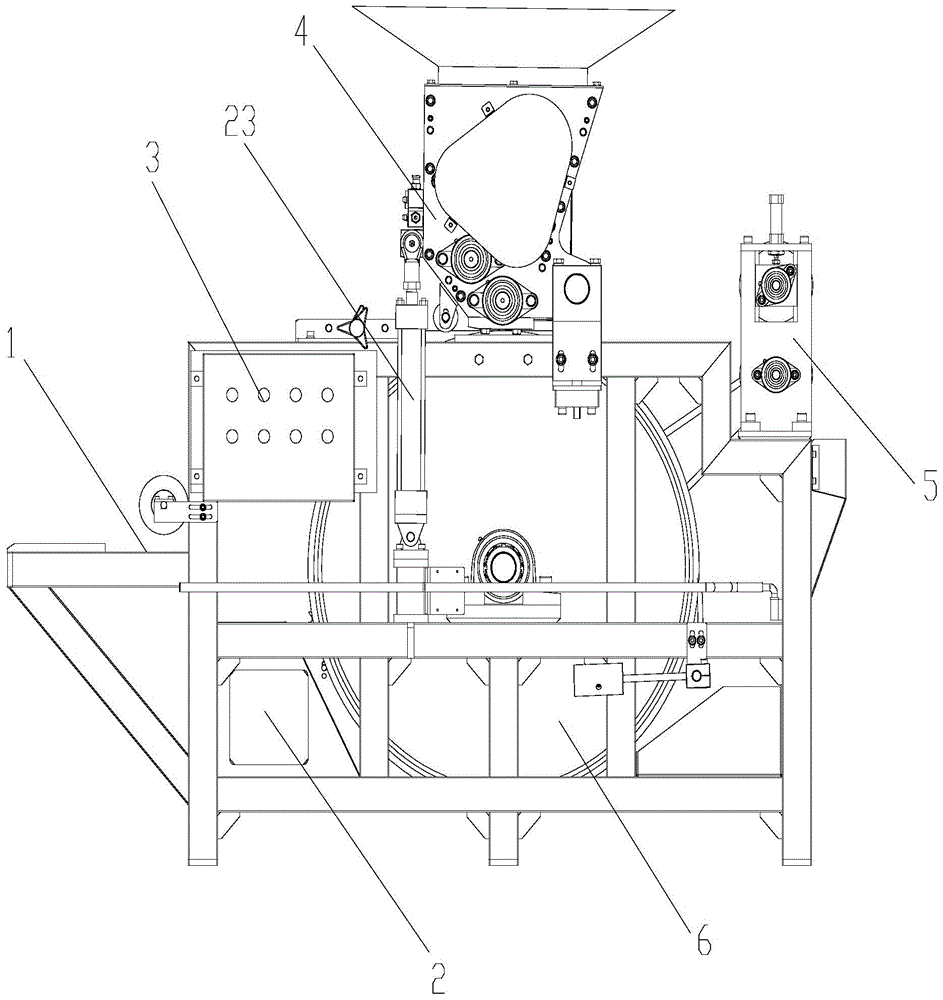
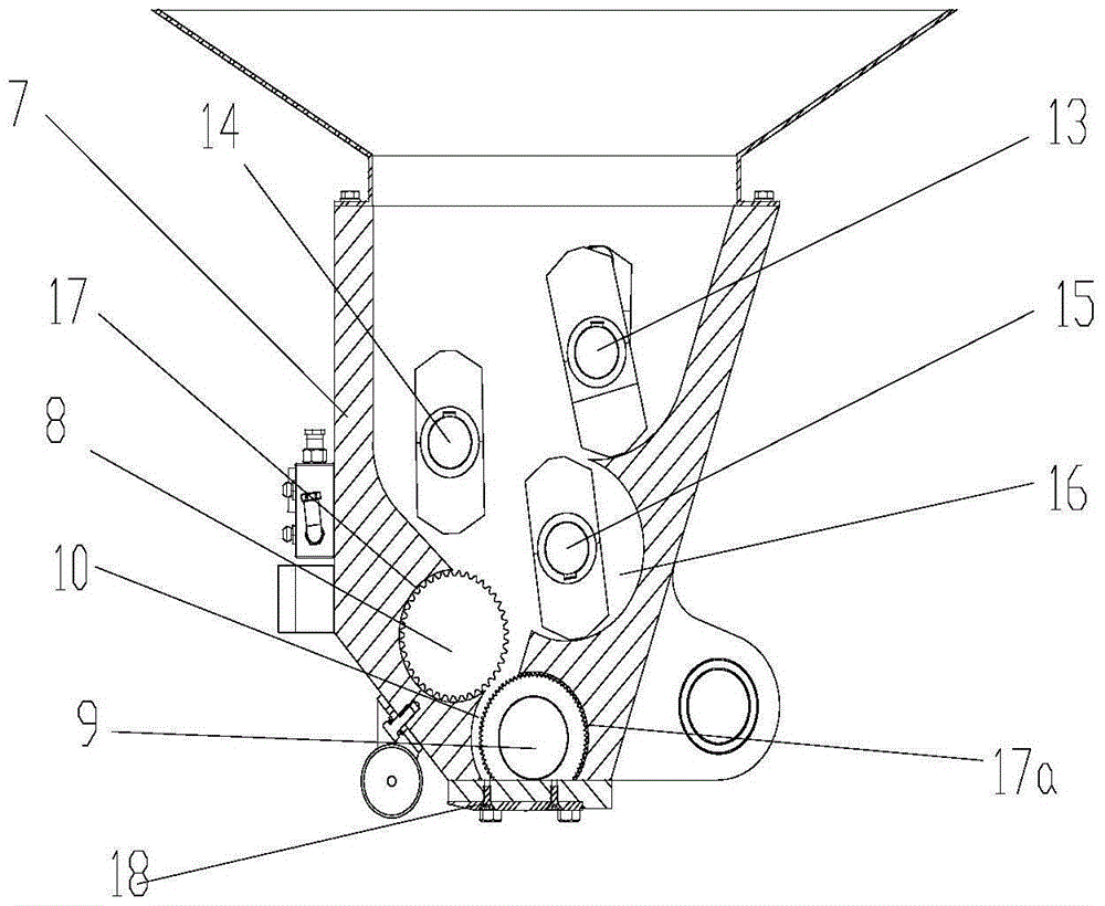
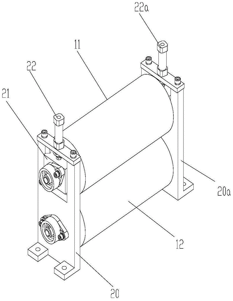
[0023] figure 1 It is a schematic diagram of the overall structure of the present invention, figure 2 Schematic diagram of the structure of the paste coating device, image 3 Schematic diagram of the traction device structure, Figure 4 It is a schematic diagram of the structure of the drum, as shown in the figure: the battery coating machine of this embodiment includes a coating host 1, a hydraulic power system 2 and an electrical control system 3, and also includes a pasting device 4, a traction device 5 and a working platform 6;

[0024] The plastering device 4 includes a plastering hopper 7 and a plaster extruding assembly and a plaster pushing assembly arranged in the plastering hopper 7, and the plaster extruding assembly includes at least one The agitating blade arranged in the plastering hopper and used to squeeze the lead paste downwards, the plaster pushing assembly includes an upper plastering roller 8 and a lower plastering roller 8 which are arranged in relativ...


PUM

PropertyMeasurementUnit
diameteraaaaaaaaaa

Abstract

The invention discloses a storage battery coating machine which comprises a coating main engine, a hydraulic power system and an electric control system, and also comprises a pasting device, a traction device and a working platform, wherein the pasting device comprises a pasting hopper and a lead plaster extrusion component and a lead plaster push component which are arranged in the pasting hopper; the lead plaster extrusion component comprises at least one stirring blade which is arranged in the pasting hopper in a mode of rotating around an own axis and is used for extruding lead plaster downwards; the lead plaster push component comprises an upper pasting roller and a lower pasting roller which are rotatably arranged opposite to each other and push the lead plaster extruded by the stirring blade downwards; a lead plaster descending channel is formed among the upper pasting roller, the lower pasting roller and the inner wall of the pasting hopper; a paste outlet is formed in the lower end of the pasting hopper. During operation, the storage battery coating machine has high operating stability, a phenomenon that deviation of weight and thickness of a polar plate is caused due to instable operation is avoided, the problem that the coating strip is easily damaged and needs to be frequently replaced can be solved, the production cost is reduced, and waste and pollution of the lead plaster can be greatly reduced.

Description

technical field [0001] The invention relates to the field of accumulator pole plate generation, in particular to an accumulator plate coating machine. Background technique [0002] With the rapid development of the battery industry, the demand for batteries is increasing, and the requirements for reducing the cost of batteries are getting higher and higher. With the emergence of continuous production lines, traditional lead-acid battery coating equipment can no longer meet the requirements. There is an urgent need A high-efficiency, high-precision, low-pollution and easy-to-maintain equipment replaces traditional products. [0003] Existing battery coating machines mostly use the coating belt as the coating working platform. The coating belt is easily damaged and needs to be replaced frequently, which not only affects the coating efficiency of the battery plate, but also increases the production cost. Moreover, the apparent density of the lead paste Larger, if the equipment...

Claims


Application Information

Patent Timeline
Patent Type & Authority Patents(China)
IPC IPC(8): H01M4/20
CPCH01M4/0404H01M4/20Y02E60/10
Inventor 熊金磊叶荣卒袁炯魏治千王菊艳
Owner 中国船舶重工集团衡远科技有限公司
Why Eureka
Try Eureka