Rotating unit type double-frequency circular polarization reflective array antenna

A technology of reflectarray antenna and rotating unit, which is applied in the electronic field, can solve the problems of application limitation, complex structure, and higher and higher requirements, and achieve the effects of reducing mutual coupling, widening bandwidth, and simple array structure

Inactive Publication Date: 2014-04-16
XIDIAN UNIV
View PDF7 Cites 24 Cited by
  • Summary
  • Abstract
  • Description
  • Claims
  • Application Information

AI Technical Summary

Problems solved by technology

In order to solve the mutual coupling problem of two similar frequencies, foreign scholars such as M.R.Chaharmir once proposed a dual-frequency reflectarray (12 / 14GHz) with a circular unit structure slotted along the orthogonal direction, but this structure is too complicated and only It is suitable for orthogonal linear polarization of two frequencies, and circular polarization of two frequencies cannot be realized, so its application is greatly limited
[0004] Although the existing dual-frequency circularly polarized reflectarray antenna has been initially applied, the structure and design of the dual-frequency reflectarray with two similar frequency bands is relatively simple, maintaining good isolation of different frequency units, and realizing circular polarization. increasingly demanding

Method used


Image

  • Rotating unit type double-frequency circular polarization reflective array antenna
  • Rotating unit type double-frequency circular polarization reflective array antenna
  • Rotating unit type double-frequency circular polarization reflective array antenna

Examples


Embodiment Construction

[0025] The present invention is described in further detail below in conjunction with accompanying drawing:

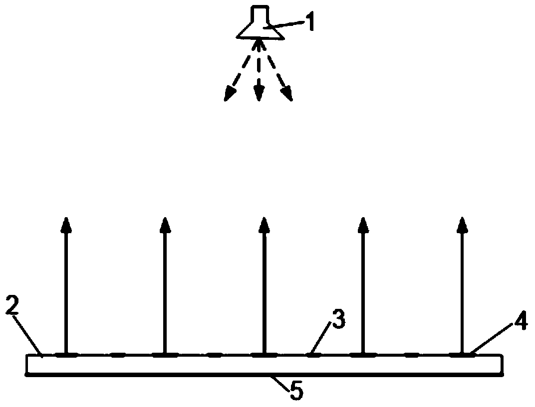
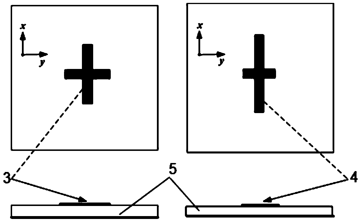
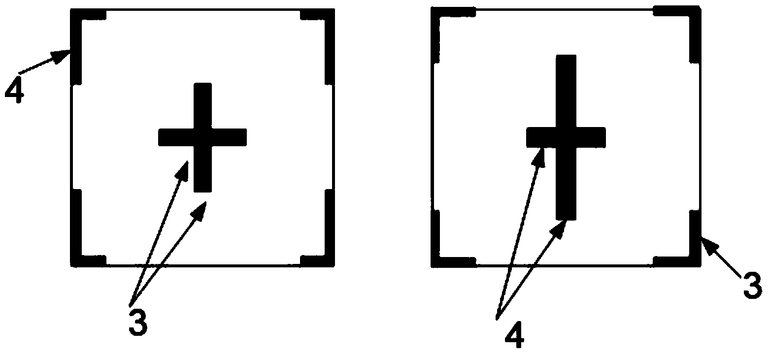
[0026] see Figure 1-12 , including a circularly polarized feed source and a reflector array. The circularly polarized feed source is composed of an axial mode helical antenna, and the reflector array is composed of high-frequency units and low-frequency units arranged alternately on a metal floor. Both the high-frequency unit and the low-frequency unit perform phase compensation in the manner of rotating the frequency unit, so as to ensure that the reflective array can emit circularly polarized beams in the same phase in both frequency bands after being irradiated by the feed source. There is a 2-fold functional relationship between the rotation angle of the unit and the required phase compensation. The phase compensation of the array unit is calculated from the phase compensation publicity of the reflectarray antenna. After obtaining the phase compensation of each un...


PUM


Abstract

The invention discloses a rotating unit type double-frequency circular polarization reflective array antenna which comprises a circular polarization feed source and a reflective array. The circular polarization feed source comprises an axial mode spiral antenna. The reflective array is formed by a high band unit and a low band unit in an alternating-arraying mode. The high band unit and the low band unit carry out phase compensation in a rotating-band-unit mode, and accordingly the fact that after feed source irradiation, the reflective array can emit identical-phase circular polarization wave beams at the two bands can be guaranteed. A rotating technology is introduced to the units at the two bands on the same layer of array face, and cross coupling between the two bands is effectively lowered. The reflective array is of a single-layer structure, so that the array structure is simple and light.

Description

Technical field: [0001] The invention belongs to the field of electronics, and relates to a dual-frequency circular polarization reflection array antenna, in particular to a rotating unit type dual-frequency circular polarization reflection array antenna. Background technique: [0002] In recent years, reflectarray antennas have been widely used in satellite communications due to their advantages such as low profile, small footprint, light weight, and easy conformity with the carrier. With the development of technology, some antennas are usually required to achieve dual-band work in microwave systems to overcome the defect of narrow frequency bands and circular polarization to enhance the anti-interference ability of antennas. In view of the many advantages of the reflectarray antenna, how to combine the dual-frequency circular polarization technology with the reflectarray antenna has been highly valued by researchers at home and abroad. [0003] Traditional dual-frequency ...

Claims


Application Information

Patent Timeline
Patent Type & Authority Applications(China)
IPC IPC(8): H01Q21/24H01Q1/52
Inventor 钟显江陈蕾余剑锋王超史小卫
Owner XIDIAN UNIV
Why Eureka
Try Eureka