Plasma column compressor

A plasma arc and compressor technology, applied in the field of ion arc column compressors, to achieve the effect of high energy density

Inactive Publication Date: 2014-04-23
SHANGHAI JIAO TONG UNIV
View PDF5 Cites 5 Cited by
  • Summary
  • Abstract
  • Description
  • Claims
  • Application Information

AI Technical Summary

Problems solved by technology

[0006] Based on the above, after searching the existing technologies of the plasma cutting torch, it is found

Method used


Image

  • Plasma column compressor
  • Plasma column compressor

Examples


Embodiment Construction

[0016] The present invention will be described in detail below in conjunction with specific embodiments. The following examples will help those skilled in the art to further understand the present invention, but do not limit the present invention in any form. It should be noted that those skilled in the art can make several modifications and improvements without departing from the concept of the present invention. These all belong to the protection scope of the present invention.

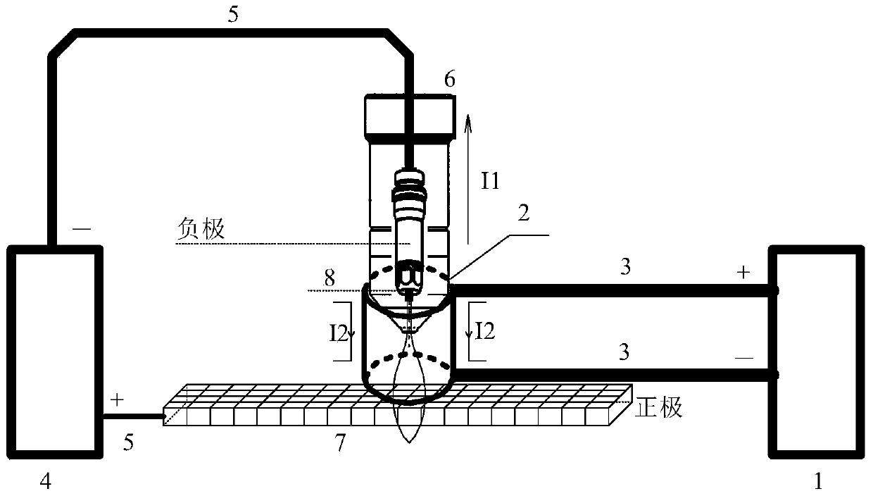
[0017] Such as figure 1 As shown, the present invention provides a plasma arc column compressor, including a compression system and a cutting system, wherein the compression system includes a compression current source 1, a compression sleeve 2 and a compression wire 3 to complete the compression of the original plasma arc column; The cutting system includes the original cutting current source 4, cutting wire 5, cutting torch 6 and workpiece 7. The inside of the cutting torch 6 has a negative elec...


PUM


Abstract

The invention provides a plasma column compressor. The plasma column compressor comprises a compression system and a matched cutting system, wherein the compression system comprises a compression current source, a compression sleeve and a compression lead, and is used for compressing an original plasma column; the matched cutting system comprises an original cutting current source, a cutting lead, a cutting torch and a workpiece, and is used for cutting a metal tube plate. Since the plasma column can be thinned by compressing, and energy is centralized, the advantages of high response speed, narrower notch, reliability and stability in running and the like are realized, and the cutting quality is closer to the lower limit level of precision cutting and laser-like cutting.

Description

technical field [0001] The invention relates to a cutting torch auxiliary device for plasma cutting in the fields of plasma cutting and power electronic conversion, in particular to a plasma arc column compressor. Background technique [0002] Whether it is manual, semi-automatic, or fully automatic cutting, the plasma cutting device is composed of mechanical equipment, electric control equipment, gas supply equipment, etc. The electric control equipment includes power supply system, numerical control system, cutting torch system and ECAN bus. Including plasma cutting power supply, arc strike box, air control box, cooling system, pipeline and other main parts. The cutting torch system includes cutting torch, horizontal servo controller and height controller controller. [0003] The power circuit of the plasma cutting device is gradually increasing. The cutting current has been developed from 130A, 260A, 400A, 530A, 650A, 800, and 1000A for cutting thicker metal sheets and p...

Claims


Application Information

Patent Timeline
IPC IPC(8): B23K10/00
CPCB23K10/00
Inventor 杨喜军陆飞唐厚君
Owner SHANGHAI JIAO TONG UNIV
Why Eureka
Try Eureka