Machine tool multiple motion shaft parallelism detecting device and method

A detection device and motion axis technology, applied in the direction of measuring/indicating equipment, metal processing machinery parts, metal processing equipment, etc., can solve the problems of cumbersome measurement steps, errors, and difficult digital processing, etc., to achieve real-time monitoring of parallelism, easy The process of building and parallelism adjustment is simple and feasible

Active Publication Date: 2014-04-23
武汉飞能达激光技术有限公司
View PDF8 Cites 5 Cited by
  • Summary
  • Abstract
  • Description
  • Claims
  • Application Information

AI Technical Summary

Problems solved by technology

[0006] 1. The side of the motion shaft contacted by the dial gauge is required to be parallel to the direction of motion of the shaft, and the side of the motion shaft and the direction of motion are affected by machining accuracy and assembly, so there are many error factors;
[0007] 2. The offset in the X and Y directions needs to be measured separately, and the measurement steps are cumbersome;
[0008] 3. The measurement results are not intuitive enough, and are not easy to be processed digitally, and often require manual calculation and processing in the later stage

Method used


Image

  • Machine tool multiple motion shaft parallelism detecting device and method
  • Machine tool multiple motion shaft parallelism detecting device and method
  • Machine tool multiple motion shaft parallelism detecting device and method

Examples


Embodiment Construction

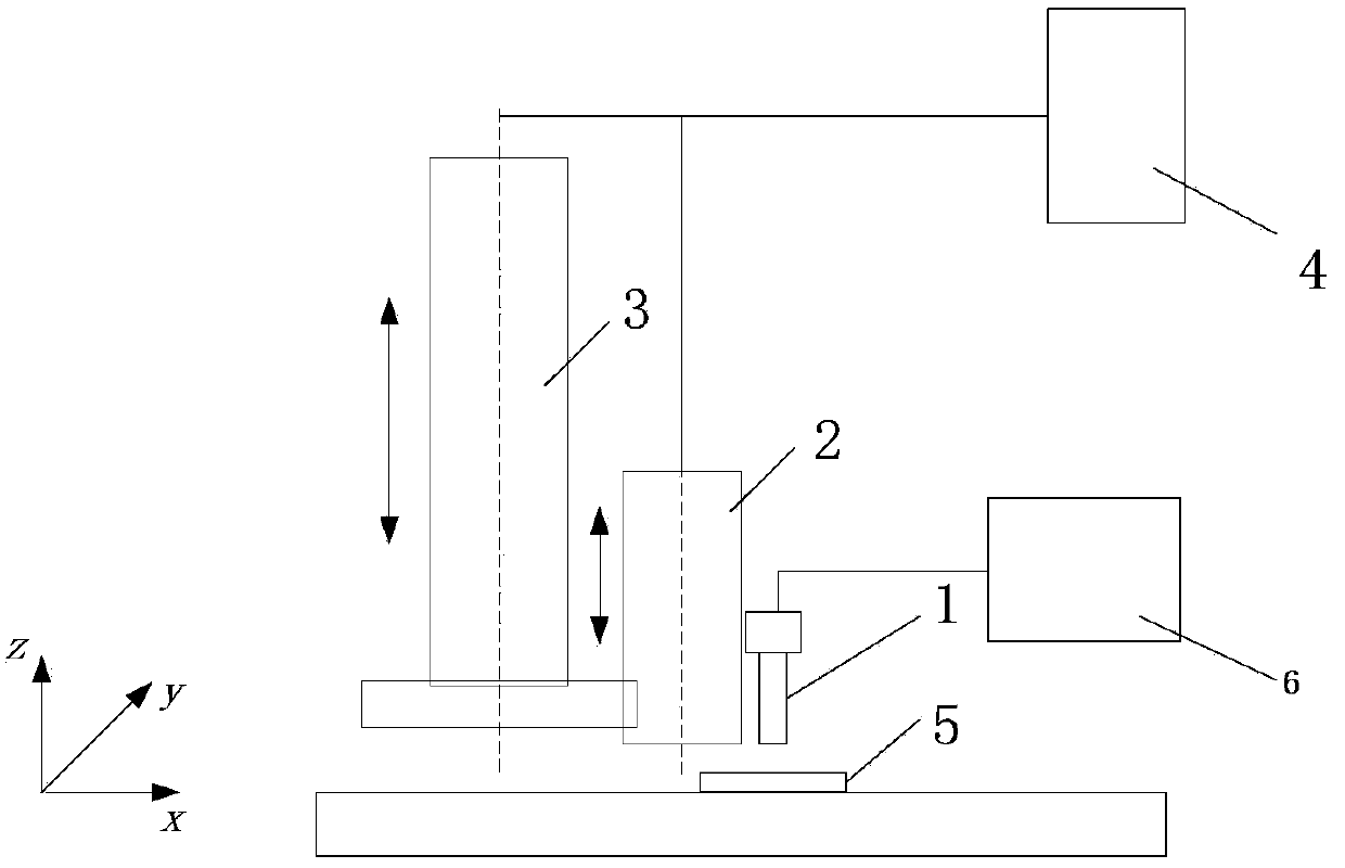
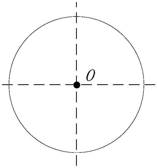
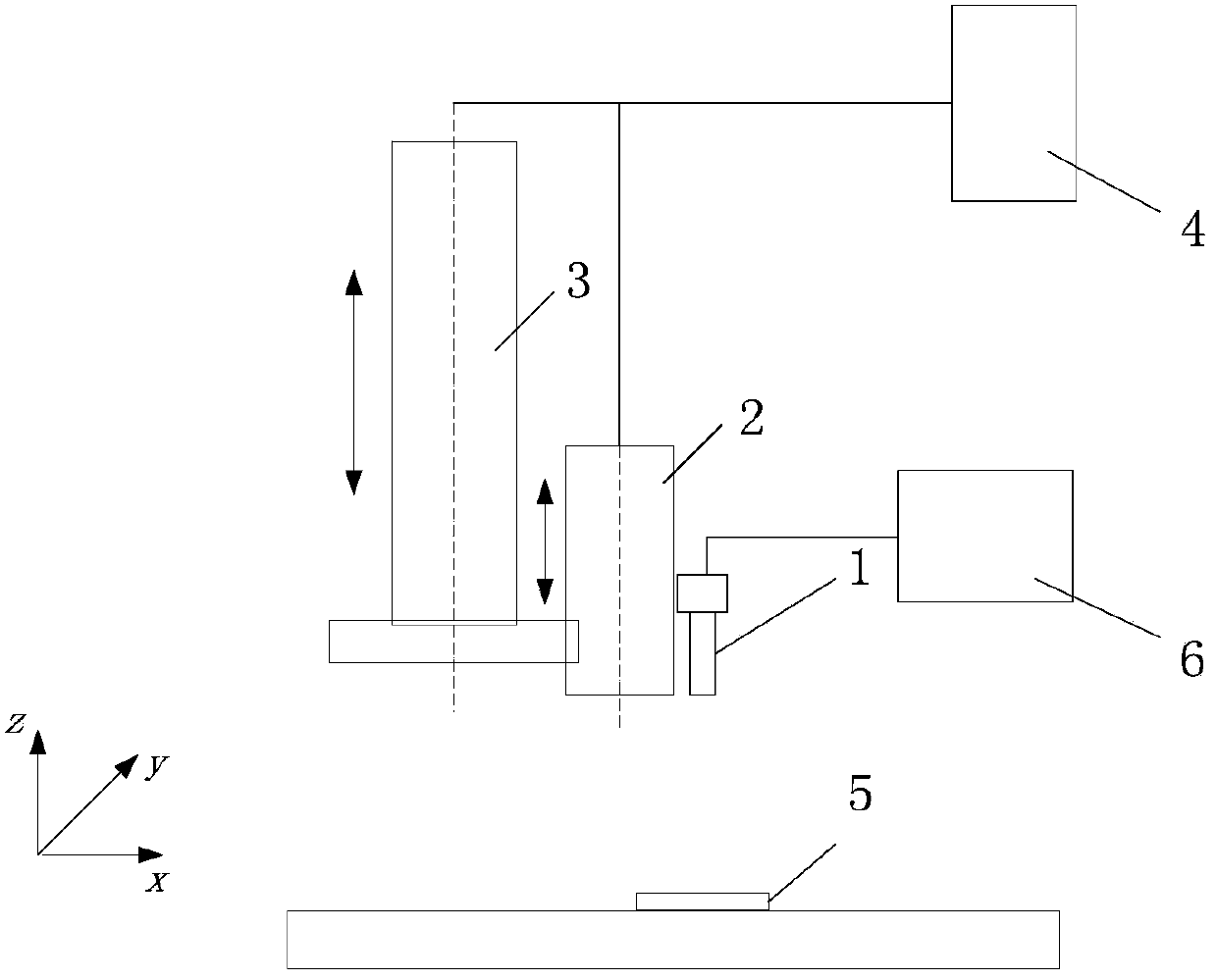
[0030] The invention realizes multi-motion axis parallelism detection by controlling the combined complementary motion of two or more parallel motion axes of the machine tool, and utilizing the CCD to detect the offset of the observation point on the calibration plate. The basic idea is to fix the CCD measuring device on the motion axis to be detected, and control the motion axis to be detected to move to the upper limit. The main motion axis drives the motion axis to be detected to move downward so that the observation point P on the calibration plate is clearly displayed on the measurement display system. Move the calibration plate horizontally so that the observation point P coincides with the central reference point O on the measurement display system. The main axis of motion moves upward by a distance H, and the axis to be detected moves downward by a distance H. At this time, the observation point P on the calibration plate is displayed at point O' on the measurement dis...


PUM


Abstract

The invention discloses a machine tool multiple motion shaft parallelism detecting device and method. The machine tool multiple motion shaft parallelism detecting device and method achieves multiple motion shaft parallelism detection by controlling the combined complementary motion of two or more parallel motion shafts and through the offset of an observing point P on a CCD (charge control device) detection calibration board. The method comprises that the CCD measurement device is fixed onto a motion shaft to be detected, and the motion shaft to be detected is controlled to move to an upper limit position; a main motion shaft drives the motion shaft to be detected to move downwards to enable the P to be presented on a measurement display system; a horizontal movement calibration board enables the P to coincide with the central datum point O of the measurement display system; the main motion shaft moves axially at a distance of H, the motion shaft to be detected moves downwards at a distance of H, and meanwhile, the P of the calibration board is displayed on the measurement display system as a point of O', therefore, the parallelism of the two motion shafts can be calculated by calculating the pixel position offset between the O and the O' and according to the resolution rate of the CCD measurement device. The machine tool multiple motion shaft parallelism detecting device and method achieves convenient and rapid non-contact motion shaft two-dimensional parallelism measurement and improves the efficiency of measuring and adjusting the multiple motion shaft parallelism.

Description

technical field [0001] The invention relates to the field of machine tool detection, in particular to a detection device and method for the parallelism of multiple motion axes of a machine tool. Background technique [0002] In the field of advanced manufacturing, more and more people are connecting other motion units on the main motion axis to realize a more flexible motion system and complete more complex processing tasks. For example, the Chinese patent document CN201881047U "a multi-axis numerical control laser processing device", by connecting the laser processing head to the end of the numerical control machine tool, the processing of larger-sized parts is completed. Chinese patent document CN102151984A "a laser processing method and device suitable for complex curved surfaces", by connecting a laser processing head with two-axis laser galvanometer and Z-axis movement to a five-axis linkage machine tool, the surface laser processing of free-form surfaces is completed. ...

Claims


Application Information

Patent Timeline
Patent Type & Authority Applications(China)
IPC IPC(8): B23Q17/00
CPCB23Q17/007B23Q17/2409B23Q17/2452
Inventor 蒋明王曦照曾晓雁段军
Owner 武汉飞能达激光技术有限公司
Why Eureka
Try Eureka