
Lower flange anti-pulling composite box girder with corrugated steel webs and construction method

A technology of corrugated steel webs and construction methods, which is applied in the direction of bridges, bridge construction, erection/assembly of bridges, etc., can solve the problem of reducing the structural performance, safety and durability of composite box girders, and restricting the promotion and promotion of corrugated steel web composite boxes. Application, lack of mechanical performance of the lower flange and difficulty of construction, etc., to improve structural performance and long-term performance, ensure safety and work performance, and reduce steel structure welding work

Inactive Publication Date: 2014-04-23
TSINGHUA UNIV
View PDF6 Cites 7 Cited by
  • Summary
  • Abstract
  • Description
  • Claims
  • Application Information

AI Technical Summary

Problems solved by technology

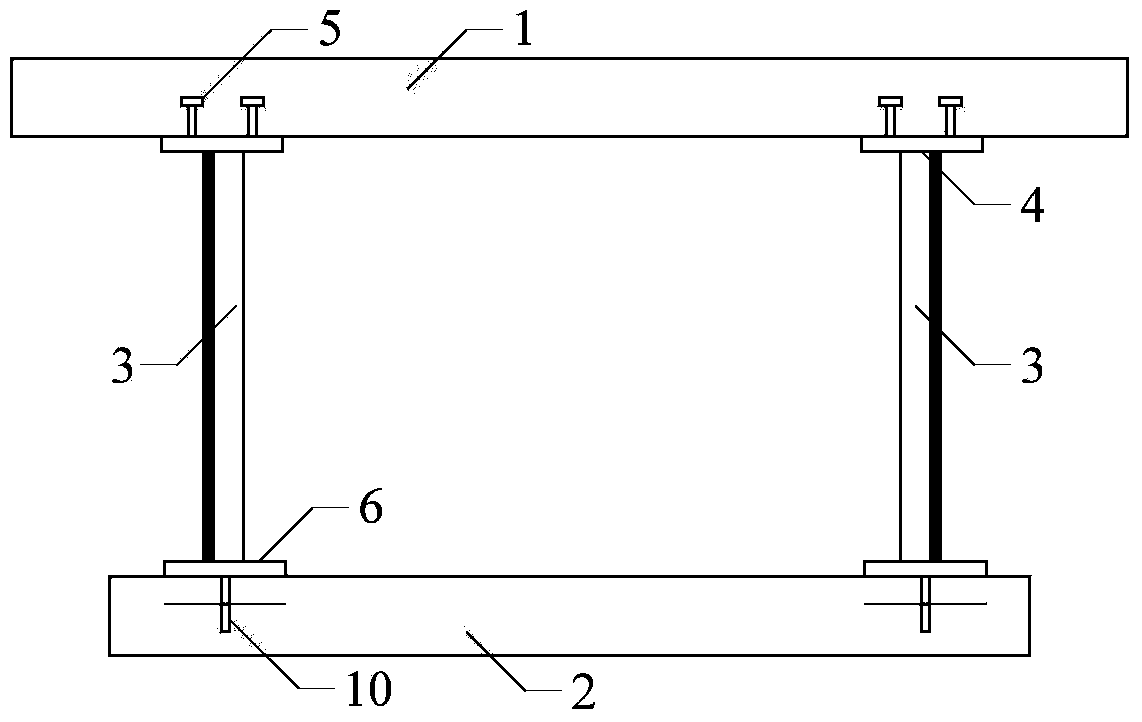
[0003] The PBL connector 10 is widely used in existing projects of this type. However, the connector has the following two deficiencies when it is applied to the lower flange of the corrugated steel web composite box girder: 1. The PBL connector 10 is longitudinally The originally complete lower flange concrete slab 2 was divided into three parts, destroying the integrity of the lower flange concrete slab 2, and adversely affecting the cooperative work of the full section of the composite box girder and the aforementioned pull-out resistance, reducing the combined The structural performance, safety and durability of the box girder; 2. After using the PBL connector 10, the layout of the steel mesh 11 is difficult, the construction of the lower flange concrete slab 2 is difficult, and the construction quality is difficult to guarantee
Therefore, the corrugated steel web composite box girder lacks a form that takes into account both the mechanical performance of the lower flange and the construction difficulty, thus restricting the further promotion and application of the corrugated steel web composite box

Method used


Image

  • Lower flange anti-pulling composite box girder with corrugated steel webs and construction method
  • Lower flange anti-pulling composite box girder with corrugated steel webs and construction method
  • Lower flange anti-pulling composite box girder with corrugated steel webs and construction method

Examples


Embodiment Construction

[0024] Below in conjunction with accompanying drawing, structure of the present invention, construction process are further described as follows.

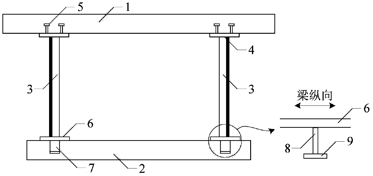
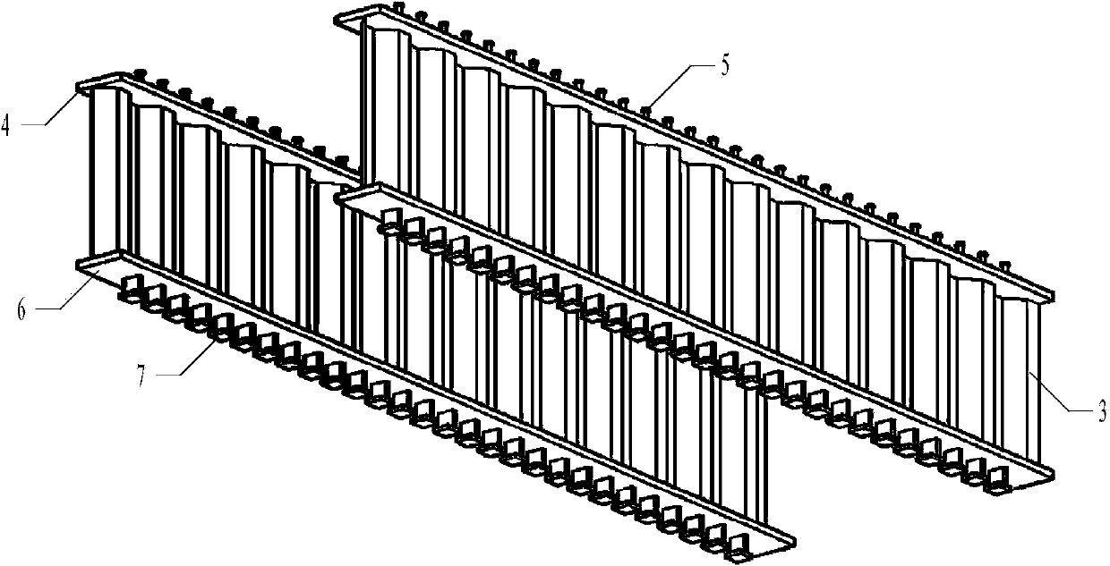
[0025] Such as figure 2 As shown, a lower flange pullout corrugated steel web composite box girder of the present invention, the composite box girder includes an upper flange concrete slab 1, a lower flange concrete slab 2, a corrugated steel web 3, an upper flange steel plate 4. The lower flange steel plate 6 and the connector 7, the corrugated steel web 3 is welded and connected with the upper flange steel plate 4 and the lower flange steel plate 6 respectively, and the lower flange concrete plate 2 is connected by welding under the lower flange steel plate 6 The upper flange concrete slab 1 is integrated with the upper flange steel plate 4 through the stud connector 5 welded on the top of the upper flange steel plate 4; the above-mentioned connection below the lower flange steel plate 6 The part is a T-shaped connector 7, whic...


PUM


Abstract

The invention relates to a lower flange anti-pulling composite box girder with corrugated steel webs and a construction method of the composite box girder, and belongs to the technical field of bridge structures. The composite box girder comprises an upper flange concrete slab, a lower flange concrete slab, the corrugated steel webs, upper flange steel plates, lower flange steel plates and connectors, the corrugated steel webs are connected with the upper flange steel plates and the lower flange steel plates, the lower flange concrete slab is integrated with the lower flange steel plates through the connectors welded on the lower portions of the lower flange steel plates, and the upper flange concrete slab is integrated with the upper flange steel plates through the stud connectors welded on the upper portions of the upper flange steel plates. The composite box girder is characterized in that the connectors on the lower portions of the lower flange steel plates are T-shaped connectors comprising T-shaped connector webs and T-shaped connector top plates. Without increasing steel dosage, the composite box girder solves the problems that reinforcing meshes in a traditional corrugated steel web lower flange concrete slab with PBL connectors, particularly, transverse reinforcements are difficultly constructed, and construction quality is difficultly ensured.

Description

technical field [0001] The invention relates to a lower flange pullout-resistant corrugated steel web composite box girder applied to bridge structures, belonging to the technical field of bridge structures. Background technique [0002] Such as figure 1 Shown is a corrugated steel web composite box girder using PBL connectors 10 on the traditional lower flange. The main functions of the PBL connectors 10 in the lower flange concrete slab 2 include: 1. Transmitting shear force: bearing the lower flange steel plate 6 The longitudinal shear force at the interface with the lower flange concrete slab 2 restricts the longitudinal free sliding of the interface between the two, so as to ensure that the deformation of the steel beam and the concrete slab cooperate and work together, play a combined role, and improve the section stiffness and bearing capacity; 2. Pull-out resistance: The lower flange concrete slab 2 is suspended below the lower flange steel plate 6. Under the action...

Claims


Application Information

Patent Timeline
Patent Type & Authority Applications(China)
IPC IPC(8): E01D2/04E01D21/00
Inventor 聂建国周萌
Owner TSINGHUA UNIV
Learn More