Method and device for lifting door/window glass of car

A door and window glass and lifting device technology, applied in the field of auto parts, can solve the problems of short fatigue life cycle, fast wear of parts, glass lifting and tilting, etc., and achieve the effects of high transmission precision, strong self-locking performance and flexible operation

Inactive Publication Date: 2014-04-23
十堰华恒机电科技有限公司
View PDF5 Cites 15 Cited by
  • Summary
  • Abstract
  • Description
  • Claims
  • Application Information

AI Technical Summary

Problems solved by technology

[0004] The transmission mechanism of the arm type glass lifter is a gear-tooth plate meshing transmission. Except for the gear, its main components are plate-type structures. Because it adopts a cantilever support structure and a gear-tooth plate mechanism, the working resistance is relatively large
And because the relative position between the supporting point of the l

Method used


Image

  • Method and device for lifting door/window glass of car
  • Method and device for lifting door/window glass of car
  • Method and device for lifting door/window glass of car

Examples


Embodiment 1

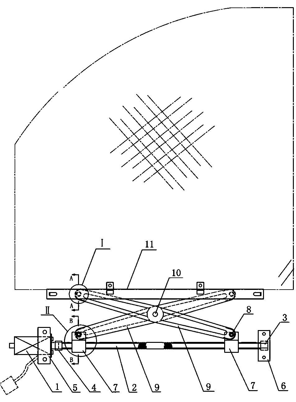
[0035] A method for lifting and lowering an automobile door and window glass, comprising the following steps:

[0036] 1) Horizontally install a motor seat and a bearing support on the inner panel of a car door;

[0037] 2) Then install the motor on the motor seat, and install the bearing on the bearing support;

[0038] 3) Set the thread structure on the lead screw into two sections on the left and right, and the two sections of threads have opposite directions of rotation and the same length, and install a nut support on the corresponding positions of the two sections of threads to form a screw pair;

[0039] 4) Connect one end of the lead screw of the above-mentioned screw pair to the output shaft of the motor, and the other end of the lead screw is sleeved on the bearing as a support;

[0040] 5) Connect the two nut supports to the lower arms of the two lifting transmission arms respectively through the rotating shaft, and the upper arms of the two lifting transmission ar...

Embodiment 2

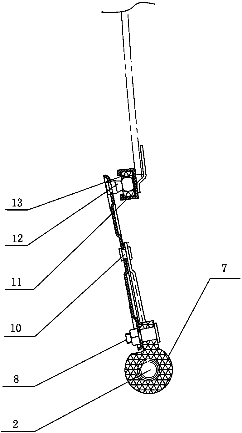
[0049] A method for lifting and lowering an automobile door and window glass, comprising the following steps:

[0050] 1) Vertically install a motor seat and a bearing support on the inner panel of a car door;

[0051] 2) Then install the motor on the motor seat, and install the bearing on the bearing support;

[0052] 3) Install a nut support on the thread position of the lead screw to form a screw pair;

[0053] 4) Connect one end of the lead screw of the above-mentioned screw pair to the output shaft of the motor, and the other end of the lead screw is sleeved on the bearing;

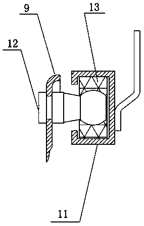
[0054] 5) The nut support of the above-mentioned helical pair is connected with a glass carriage through a ball head sliding rod;

[0055] 6) Install the glass on the glass carriage through the glass guide channel;

[0056] 7) Turn on the power switch, and the motor drives the lead screw of the screw pair to rotate;

[0057] 8) When the lead screw rotates, it converts the rotary motion into linea...


PUM


Abstract

The invention provides a method and a device for lifting door/window glass of a car. A motor drives a lead screw of a screw pair to rotate, rotary motion is changed into linear motion to generate a relatively great transmission ratio, a relatively great axial thrust is obtained by the virtue of a relatively small torque so as to drive glass on a lifting drive arm or a glass dragging plate to move up and down to realize lifting. The method is high in transmission precision and strong in self-locking performance. The device for realizing the method has two modes, i.e., a horizontal transmission mode and a vertical transmission mode, and comprises a motor, the screw pair and a bearing; one end of the lead screw of the screw pair is connected to the output shaft of the motor while the other end thereof is supported through the bearing; a nut support of the screw pair is connected to the lifting drive arm or the glass dragging plate; the lifting drive arm is connected to a sliding guide rail; glass is mounted on the sliding guide rail or the glass dragging plate. The device is simple in structure, flexible to operate, low in cost, long in service life, and suitable for glass doors/windows with different camber lines.

Description

technical field [0001] The invention relates to the field of auto parts, in particular to a method for lifting and lowering an automobile door and window glass and a lifting device. Background technique [0002] With the continuous progress and development of the automobile industry, people have higher and higher requirements for automobile performance. The door and window glass of the car not only needs to ensure that the driver has enough viewing angles to achieve the purpose of driving safely; at the same time, in order to meet the needs of riding comfort, the position of the glass often needs to be adjusted, so the adjustment range and maneuverability of the glass become a measure of car performance. an important indicator. [0003] The mechanism used to adjust the glass of the car is the glass regulator, which is also an important part that affects the safety and comfort of the car. The glass regulator refers to a device that raises or lowers the car window glass alon...

Claims


Application Information

Patent Timeline
IPC IPC(8): E05F15/16E05F15/697
Inventor 张汉龙
Owner 十堰华恒机电科技有限公司
Why Eureka
Try Eureka