
Wind power generation device

A technology of wind power generation device and wind direction, which is applied in the direction of wind power generator, wind power motor combination, wind power motor control, etc. It can solve the problems of damage to wind power equipment, poor quality of parts and low wind energy conversion efficiency, etc., and achieves the improvement of rotation speed and Intensity, minimal impact on the environment, and the effect of improving utilization efficiency

Inactive Publication Date: 2014-04-23
彭再军
View PDF5 Cites 1 Cited by
  • Summary
  • Abstract
  • Description
  • Claims
  • Application Information

AI Technical Summary

Problems solved by technology

[0004] 1. The conversion efficiency of wind energy is relatively low; 2. The technical level of domestic wind turbines needs to be improved, and there are still major problems in the overall quality, and the quality of some domestic parts is still not up to standard; 3. Traditional wind turbines are often made very large in order to increase the force bearing area of ​​the wind. Correspondingly, the supporting fan pillars are also very large, so the manufacturing cost of the whole fan is very high, and the requirements for the material of the fan blades are extremely high, otherwise it will be easily damaged in strong winds.
Although most of the traditional fans currently use special materials, damage to the fan equipment often occurs when the wind level is relatively high

Method used


Image

  • Wind power generation device
  • Wind power generation device
  • Wind power generation device

Examples


Embodiment Construction

[0018] The present invention will be further elaborated below in conjunction with the accompanying drawings and specific implementation examples.

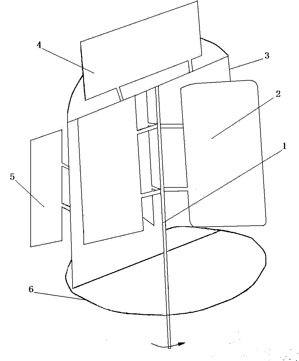
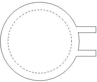
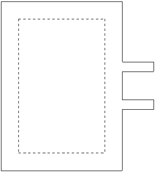
[0019] From figure 1 It can be seen that the wind power generation device of the present invention includes a blade set, a shield cover, and a central shaft, the blade set is composed of two or more blades and the blade set is connected to the central shaft, and the central shaft is connected to the generator shaft or the energy storage transmission mechanism , the shielding case is a hollow semi-cylindrical shape, there is a wind direction adjustment plate on the top of the shielding case and the arc portion of the side of the shielding case, there is a slewing bearing mechanism on the bottom of the shielding case, or there is a groove evenly distributed with balls Circular trough, the shield cover can be adjusted and moved 360 degrees around the central axis on a fixed slewing bearing or other circular trough mechanism according ...


PUM


Abstract

The invention discloses a wind power generation device. The wind power generation device is characterized by comprising a blade group, a shielding cover and a central shaft. The blade group consists of two or more blades and is connected with the central shaft, the central shaft is connected with a generator rotary shaft or an energy storage and transfer mechanism, the shielding cover is in a shape of a hollow half-cylinder, the top of the shielding cover and the side circular-arc portion of the shielding cover are respectively provided with a wind direction adjusting plate, a rotary supporting mechanism and a round groove provided with evenly-distributed balls is arranged at the bottom of the shielding cover, and the shielding cover perform 360-degree motion around the central shaft on the fixed rotary supporting mechanism or other round groove mechanisms. The wind power generation device is very high in wind power conversion efficiency, the fan manufacturing cost is low, the whole device parts can be made of common materials and meet the requirements, and special materials are not required. In addition, the device is not easily damaged, excellent performances of breeze starting, noiselessness, resistance on higher than level 12 typhoon, proofing of wind direction influence and the like are achieved, the wind power generation device can be used for a large number of different windy environments and a power generation system built based on the wind power generation device has the advantages of being stable in power output, having small influence on the environments and the like.

Description

technical field [0001] The invention relates to a wind energy utilization technology, in particular to a wind power generating device. Background technique [0002] According to the current feed-in tariff and power generation cost of wind power, it is not attractive to invest in wind farms. The development of China's wind power industry is mainly driven by the government. The National Development and Reform Commission stipulated in the "Renewable Energy Medium and Long-term Development Plan" that by 2010 and 2020, the non-hydropower renewable energy power generation The total equity installed capacity should reach more than 3% and 8% of its total equity power generation installed capacity. It is precisely because of the government's mandatory quota that drives large power generation companies to invest in wind power. Wind power is not only environmentally friendly and renewable, but also has low cost, short construction period, and no fuel restrictions. It is the most prom...

Claims


Application Information

Patent Timeline
Patent Type & Authority Applications(China)
IPC IPC(8): F03D9/00F03D3/00F03D3/04F03D3/06F03D7/06
CPCY02E10/74Y02P70/50
Inventor 彭再军
Owner 彭再军
Learn More