
Safety linkage locking device for quick valve of pressure vessel

A pressure vessel and locking device technology, applied in the field of pressure vessels, can solve problems such as hindering structure popularization, failure, manufacturing errors, etc., and achieve the effect of convenient operation and stable performance

Inactive Publication Date: 2014-04-23
ZHEJIANG DONGOU FILTERING MASCH MFG CO LTD
View PDF7 Cites 9 Cited by
  • Summary
  • Abstract
  • Description
  • Claims
  • Application Information

AI Technical Summary

Problems solved by technology

However, the device of the wrong-toothed quick-opening door requires high matching precision and high machining requirements.
At present, the maximum diameter of the door hole can only be 1.2 meters, and it is quite difficult to make a larger diameter
On the other hand, since all the pressing surfaces of the device are very close to the edge of the door hole, corrosive materials encountered in the production process can easily corrode the seals of the wrong teeth, making this key component fail quickly, thus hindering this structure universal
[0006] Cylinder—Multiple (single) compression hook quick-opening door locks the quick-opening door by using the wedge iron on the compression hook and the inclined iron on the flange due to the friction angle to produce a mechanical self-locking principle, but due to manufacturing and installation errors , under the pressure in the container, if the operation is improper, the compression hooks will be automatically decoupled due to the failure of individual compression hooks or the corrosion of the inclined surface, which poses a safety hazard

Method used


Image

  • Safety linkage locking device for quick valve of pressure vessel
  • Safety linkage locking device for quick valve of pressure vessel
  • Safety linkage locking device for quick valve of pressure vessel

Examples


Embodiment Construction

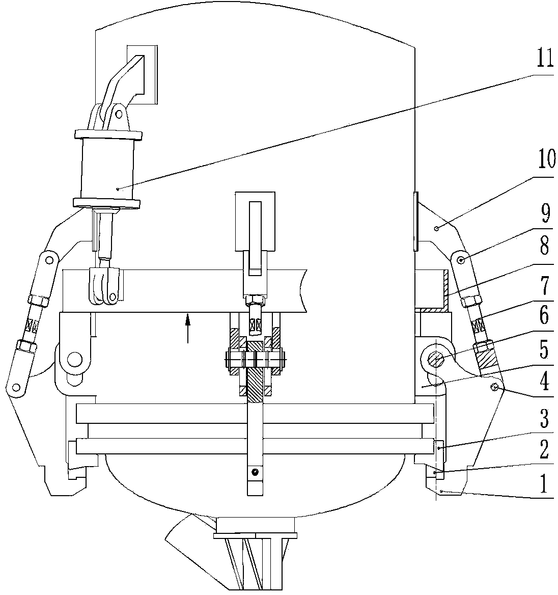
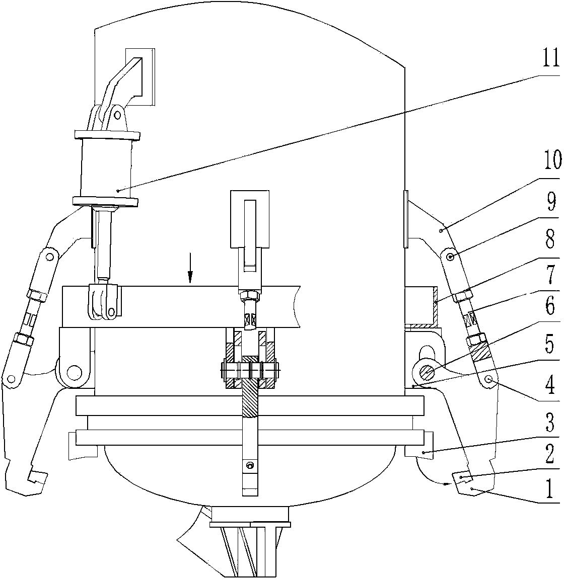
[0031] Such as Figure 1-4 As shown, the present invention provides a quick-open door safety linkage locking device for a pressure vessel, which includes a locking hook 1, an inclined iron 2, an inclined pad iron 3, a first pin shaft 4, a long-hole lifting lug 5, and a second pin shaft 6. Pull rod 7, sliding ring 8 (circular or polygonal, etc.), third pin 9, fixed lifting lug 10 and cylinder 11;

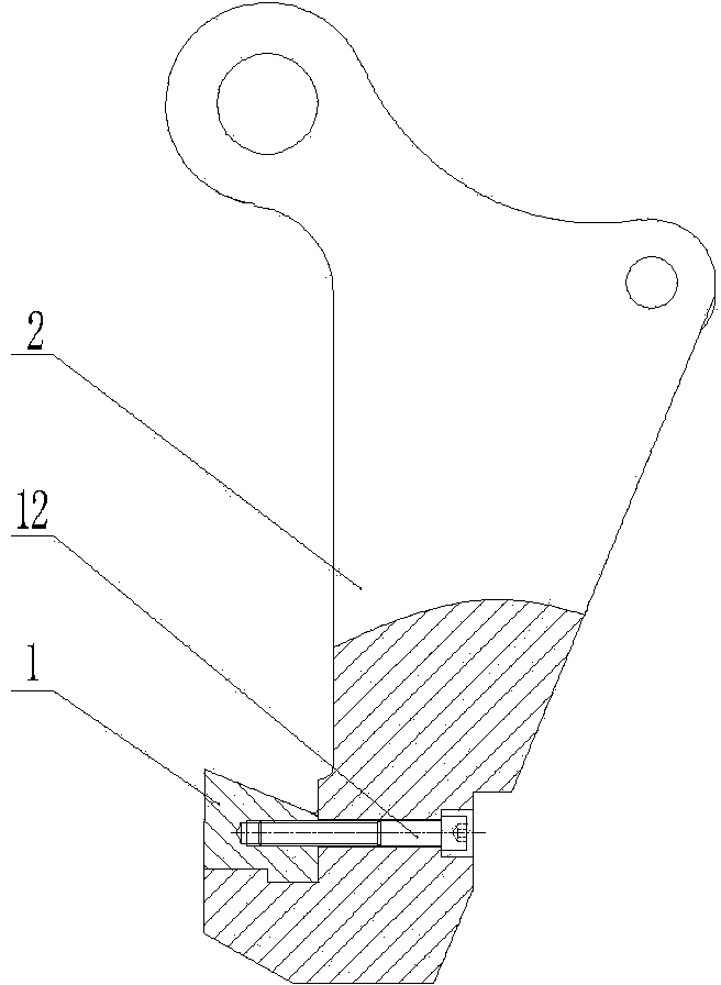
[0032] Both the long hole lifting lug 5 and the fixed lifting lug 10 are fixedly installed on the outer wall of the pressure vessel; the long hole lifting lug 5 is provided with a long hole; the sliding ring 8 is driven by the cylinder 11 to move up and down in a straight line;

[0033] The locking hook 1 includes a hook head end, a hook tail end and a curved rod connecting the hook head end and the hook tail end; the inclined iron 2 is fixedly arranged on the hook head end of the locking hook 1 through a locking screw 12; The iron 3 is installed on the flange of the pressure vessel...


PUM

PropertyMeasurementUnit
Slope angleaaaaaaaaaa

Abstract

The invention provides a safety linkage locking device for a quick valve of a pressure vessel. The safety linkage locking device comprises a locking hook, inclined iron, inclined face pad iron, a first hinge pin, a second hinge pin, a pull rod, a sliding ring, a third hinge pin, a fixing lifting lug and an air cylinder or oil cylinder. The sliding ring is driven by the air cylinder or the oil cylinder. The locking hook comprises the hook head end, the hook tail end and a bending rod connecting the hook head end and the hook tail end. The inclined iron is fixedly arranged at the hook head end. The inclined face pad iron is installed on a flange of the pressure vessel. The inclined face pad iron is matched with the inclined iron and the locking hook to form a hook mechanism. The hook tail end is connected with the sliding ring through the second hinge pin. The bending rod is connected with one end of the pull rod through the first hinge pin, and the other end of the pull rod is connected with the fixing lifting lug through the third hinge pin. The safety linkage locking device lowers the requirement for the processing and manufacturing precision of parts in the processing, manufacturing, debugging and using processes and is convenient to operate, and the linkage locking performance is stable and reliable.

Description

technical field [0001] The invention belongs to the field of pressure vessels, and in particular relates to a safety linkage locking device for a quick-opening door of a pressure vessel. Background technique [0002] During the production process of the pressure vessel, the materials in it must be processed frequently. In order to allow these materials to be freely loaded or removed, holes and door covers are provided on the pressure vessel. During the production process, the door cover needs to be frequently assembled and disassembled. Very inconvenient and labor-intensive. [0003] With the development of science and technology, in order to improve productivity and reduce labor intensity, the use of quick-opening doors is becoming more and more common. The door cover opening and closing device on the pressure vessel has also been continuously improved, and various quick-opening doors have appeared, replacing the flange of the door cover with bolts. [0004] At present, s...

Claims


Application Information

Patent Timeline
IPC IPC(8): F16J13/06
Inventor 聂孟春宋志骥陈金富俞超赵石凯胡良分
Owner ZHEJIANG DONGOU FILTERING MASCH MFG CO LTD
Learn More