Waste heat recovery thermal power plant energy storage method and system

A waste heat recovery and thermal power plant technology, applied in heating systems, hot water central heating systems, heating methods, etc., can solve problems such as insufficient heat sources and energy shortages

Inactive Publication Date: 2014-04-23
HENAN AIMOKA ENERGY SAVING TECH
View PDF5 Cites 12 Cited by
  • Summary
  • Abstract
  • Description
  • Claims
  • Application Information

AI Technical Summary

Problems solved by technology

[0003] Aiming at the current problems of energy shortage and insufficient heat source, the present invention provides an energy storage system for waste heat recovery thermal power plants, which makes full use of the peak-valley difference between the electricity consumption in the heating and cooling period and the electricity consumption in normal seasons, daytime electricity consumption and nighttime electricity consumption , the combination of energy storage and waste heat recovery will help meet the requirements of load regulation and peak regulation, realize energy storage for centralized heating of thermal power plants, expand the power generation capacity of thermal power plants during the daytime peak period of electricity consumption, expand the heat supply of thermal power plants, improve the profitability of thermal power plants, and realize thermal power plants. Industrial waste heat recovery and utilization is an energy-saving and environmental protection technology for heating and heating

Method used


Image

  • Waste heat recovery thermal power plant energy storage method and system

Examples


Embodiment Construction

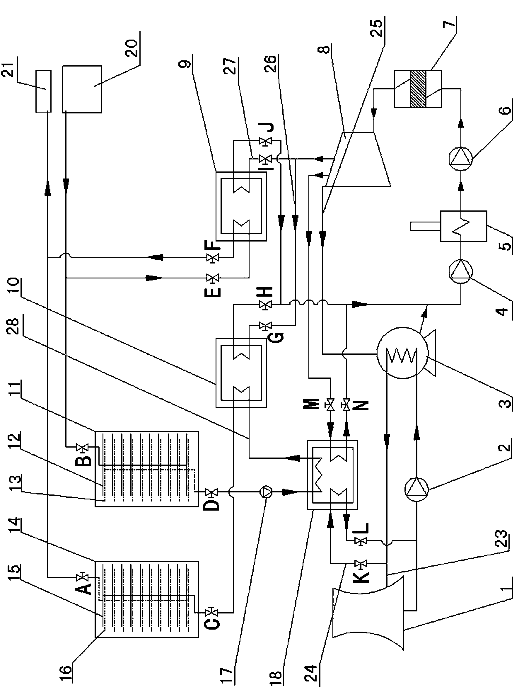
[0015] Below in conjunction with accompanying drawing, the present invention will be further described.

[0016] Such as figure 1 Shown is an energy storage method for waste heat recovery thermal power plants. During the day in the heating season, all the power generated by the power unit is used to generate electricity, and the energy storage water is used to bear the entire heating system; at night in the heating season, steam is extracted from the low-pressure cylinder of the steam turbine in the power unit. The steam extracted from the outlet drives the primary heating unit to heat the 60°C heat network return water obtained from the heat network return water unit 20 to 80°C, and then the steam turbine heats the steam extracted from the steam extraction port to drive the secondary heating unit to heat the heated water to 80°C. The return water at 80°C continues to be heated to 120°C, and the energy storage water at 120°C is used as the heat source for the heating system. ...


PUM


Abstract

The invention discloses a waste heat recovery thermal power plant energy storage method. In the daytime of a heating season, power generated by a power unit is completely used for generating electricity, and all heating systems are borne by energy storage water; at night of the heating season, steam pumped out by a steam pumping opening of a low pressure cylinder of a steam turbine in the power unit drives a first-stage heating unit to enable 60 DEG C heat supply network return water obtained from a heat supply network return water unit to be heated to reach 80 DEG C, then the steam pumped out from the steam pumping opening is heated by the steam turbine to drive a second-stage heating unit to continuously heat the heated 80 DEG C return water to reach 120 DEG C, and the 120 DEG C energy storage water serves as a heat source of the heating system. According to the waste heat recovery thermal power plant energy storage method, the load adjusting and peak adjusting requirements are easily met, the electricity shortage situation in the peak period can be remitted, the electivity resource allocation is optimized, and the electricity utilization efficiency is improved. As for a thermal power plant achieving the designed heating amount upper limit, heating energy storage is carried out at the electricity load low ebb period at night, heating by stored energy released in the daytime and heating of an original heating system are carried out at the same time, the heating capacity of the thermal power plant is improved, the earnings of the thermal power plant are improved, industrial waste heat of the thermal power plant is recycled, the comprehensive saving rate of the heating energy storage water achieves 20%, and the energy dilemma and the environmental pollution are easily remitted.

Description

technical field [0001] The invention relates to the field of energy storage for waste heat recovery and utilization, in particular to an energy storage system for waste heat recovery thermal power plants. Background technique [0002] With the rapid development of the city and the continuous improvement of people's living standards, the city's electricity consumption is also increasing, but the electricity consumption during the heating and cooling period is not balanced with that in normal seasons, and the electricity consumption during the day and at night is unbalanced. There are peak and valley differences in urban power grids, energy shortages and environmental protection issues are becoming more and more prominent. The utilization and development of new technologies and new energy sources can reduce energy costs and improve energy utilization efficiency, and achieve ideal economic benefits and harmonious development of the natural environment. New social responsibiliti...

Claims


Application Information

Patent Timeline
Patent Type & Authority Applications(China)
IPC IPC(8): F24D3/18F24D19/10F28D20/00
CPCY02E60/142Y02E60/14
Inventor 张辉李华伟高春来高丽
Owner HENAN AIMOKA ENERGY SAVING TECH
Why Eureka
Try Eureka