Circulating fluidized bed device with drying and crushing functions

A circulating fluidized bed, functional technology, used in lighting and heating equipment, drying solid materials, heating to dry solid materials, etc., can solve the problems of low output of dryer, poor circulation, complex equipment structure, etc., to achieve high output , the effect of good circulation and simple equipment structure

Inactive Publication Date: 2014-04-23
云南守一药业有限公司
View PDF11 Cites 4 Cited by
  • Summary
  • Abstract
  • Description
  • Claims
  • Application Information

AI Technical Summary

Problems solved by technology

The existing jet mill cannot dry the material, and the moisture content of the material has a great influence on the grinding efficiency, and there are also shortcomings such as complex equipment structure and the need to consume a large amount of compressed air.
[0003] Invention patent ZL2010101628876 describes a drying equipment for powder materials. The drying equipment includes a fluidized bed body for forming a fluidized state of the material and drying it, and a sieve plate net box for separating the material and gas, so that the fluidized state material Circulating circulation system and the back blowing system used to remove the materials accumulated on the sieve mesh to block the sieve mesh, etc., the equipment has the following shortcomings: First, the air velocity in the main cavity of the fluidized bed is not high, and the material with high moisture content It is difficult to form a fluidized state effectively with viscous materials; second, materials are easily deposited in the dead corner of the sieve cage; third, the sieve cage is used to separate the wet air flow, and the moisture discharge speed is slow due to the limitation of the screen area
The above deficiencies lead to poor material fluidization state, poor circulation, low output of the dryer, and it is also very difficult to process materials with high water content and viscous materials.
[0004] Existing equipment cannot simultaneously perform airflow crushing and airflow drying operations

Method used


Image

  • Circulating fluidized bed device with drying and crushing functions
  • Circulating fluidized bed device with drying and crushing functions
  • Circulating fluidized bed device with drying and crushing functions

Examples


no. 1 example

[0019] The first embodiment: a circulating fluidized bed equipment with drying and crushing functions.

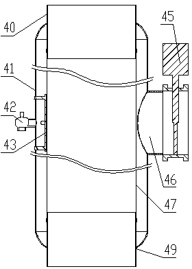
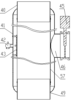
[0020] see Figure 1 to Figure 3 , the circulating fluidized bed equipment with drying and crushing functions includes a fan 1, a circulation pipeline I2, a dust collector 4, a classifying device 10, a regulating valve 5, an air inlet tee 6, and a circulation pipeline II7. Exit, circulation pipeline I2, dust collector 4 intake pipe 40, dust collector 4 ash discharge pipe 49, classification device 10 intake pipe 40, classification device 10 ash discharge pipe 49, regulating valve 5, intake tee 6, circulation pipeline Ⅱ7. The inlet of the fan 1 is connected in order to form a circulation channel; there is a discharge port on the circulation line Ⅰ2, and a discharge valve 3 is installed on the discharge port; there is a feeding port on the circulation line Ⅱ7, and a feeding valve 8 is installed on the feeding port. Another port of gas tee 6 is an air inlet, and air inlet valv...

no. 2 example

[0023] The second embodiment: a circulating fluidized bed device with drying and crushing functions.

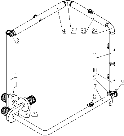
[0024] see Figure 4 , the circulating fluidized bed equipment with drying and crushing functions includes fan 1, circulation pipeline I2, dust collector 4, pipeline A22, dust collector 23, pipeline B24, classification device 11, classification device 10, regulating valve 5, air intake Tee 6, circulation pipeline II 7, fan 25, fan 26, the connection of the above-mentioned components is different from the first embodiment in that: one is to connect in series between the ash discharge pipe of the dust collector 4 and the intake pipe of the classification device 10 Pipeline A22, deduster 23, pipeline B24, and classifier 11 connected in sequence are provided. The second is that fan 25 and blower fan 26 connected in sequence are connected in series between the inlet of circulation pipeline II7 and blower fan 1.

[0025] The circulating fluidized bed equipment with drying and crus...


PUM


Abstract

The invention discloses a circulating fluidized bed device with drying and crushing functions. A circulating channel is formed by a fan (1), a circulating pipeline I (2), a dust remover (4), a regulating valve (5), an air inlet tee (6) and a circulating pipeline II (7); materials are fluidized and flow at the high speed in a circulating mode in the circulating channel under the action of the air flow produced by the fan (1); moisture exchange is performed between the materials and the air flow rapidly in the process of high-speed flow and the moisture in the material is discharged along with the air flow separated from the dust remover (4) after being vaporized; meanwhile the materials are crushed under the action of blades of the fan (1), the pipe wall and the mutual impact and accordingly the drying and crushing functions can be achieved.

Description

technical field [0001] The invention relates to a device for air drying and air crushing of powder materials. Background technique [0002] The working principle of the existing jet mill is that the compressed air is sprayed at high speed through the nozzle into the crushing chamber pre-loaded with materials, and the materials are repeatedly collided, rubbed, and sheared at the intersection of multiple high-pressure airflows, and the crushed materials are crushed. Under the action of fan suction, it moves to the classification device with the upward airflow to separate the coarse and fine materials. The fine particles that meet the particle size requirements enter the collection device through the classification device to collect, and the coarse particles descend to the crushing area to continue crushing. The existing jet mill cannot dry the material, and the moisture content of the material has a great influence on the grinding efficiency, and there are also shortcomings su...

Claims


Application Information

Patent Timeline
Patent Type & Authority Applications(China)
IPC IPC(8): F26B3/084F26B25/00B02C19/06
Inventor 夏跃金贾平曾亚文杨国荣
Owner 云南守一药业有限公司
Why Eureka
Try Eureka