Adaptive focusing optical system and focusing method

An adaptive and optical technology, applied in the electromechanical field, can solve the problems of high focusing precision, small size, and low power consumption, and achieve the effects of high focusing precision, strong intelligence, and light weight

Active Publication Date: 2014-04-23
SHANGHAI ENG CENT FOR MICROSATELLITES
View PDF6 Cites 8 Cited by
  • Summary
  • Abstract
  • Description
  • Claims
  • Application Information

AI Technical Summary

Problems solved by technology

[0004] The purpose of the present invention is to solve the problem that the focusing mechanism in the prior art has low focusing accuracy and cannot meet the task requirements of modern optical micro-satellites with light weight, small volume and low power consumption, and does not have self-adaptive focusing applied to micro-satellites To solve the problem of ability, provide an adaptive focusing mechanism, driven by piezoelectric ceramics, light in weight, small in size, and high in focusing accuracy
[0006] Another purpose of the present invention is to solve the problem that the focusing mechanism in the prior art has low focusing accuracy, cannot meet the task requirements of modern optical micro-satellites with light weight, small volume, and low power consumption, and does not have self-adaptive technology for micro-satellites. To solve the problem of focusing ability, an adaptive focusing optical system is provided, which adopts computer image processing technology and precision mechanical intelligent control technology, which can well realize the adaptive focusing of the spaceborne optical system, and has strong intelligence and excellent focusing ability. High precision, large range, small self-weight and small size of the focusing mechanism, can be applied to micro-satellites, and can prompt micro-satellites to perform adaptive focusing after the optical system is out of focus, and obtain ideal satellite images

Method used


Image

  • Adaptive focusing optical system and focusing method
  • Adaptive focusing optical system and focusing method
  • Adaptive focusing optical system and focusing method

Examples


Embodiment Construction

[0026] The specific implementation of the adaptive focusing optical system and the focusing method provided by the present invention will be described in detail below with reference to the accompanying drawings.

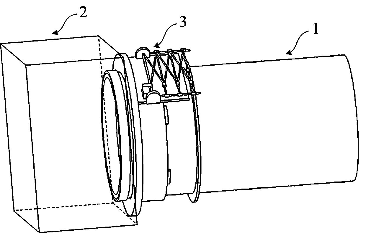
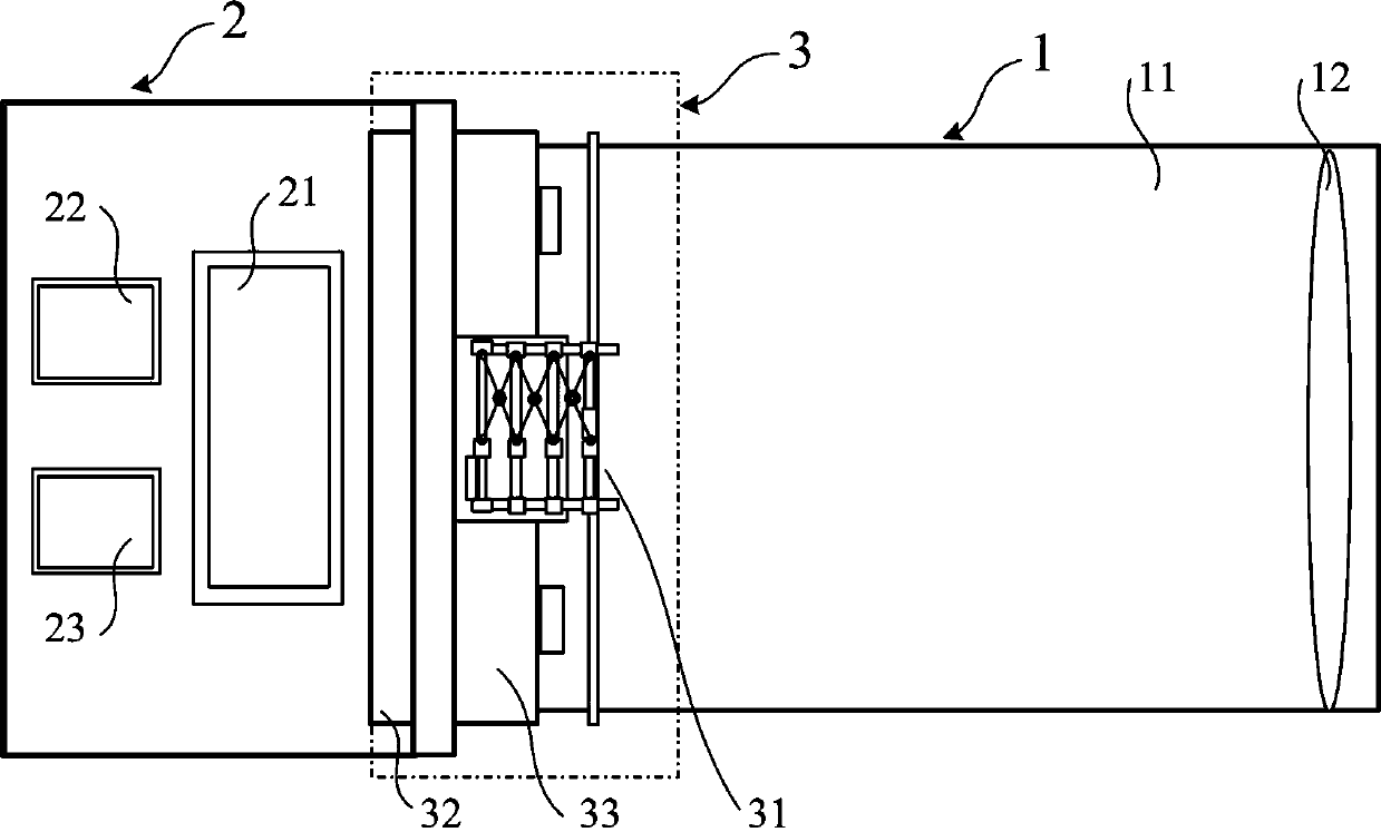
[0027] refer to Figure 1-2 ,in, figure 1 Shown is a perspective view of the adaptive focusing optical system of the present invention, figure 2 Shown is a schematic structural diagram of the adaptive focusing optical system of the present invention. The adaptive focusing optical system of the present invention includes an optical main body mechanism 1 , an electric control box 2 and an adaptive focusing mechanism 3 . With the development of image processing technology and the maturity of piezoelectric ceramic drive technology, visual servo control technology and piezoelectric ceramic high-precision mechanical design are also becoming more and more mature. Therefore, applying the precision mechanical intelligent control technology to the design of the optical sys...


PUM


Abstract

An adaptive focusing optical system comprises an optical body mechanism, an electric control box and an adaptive focusing mechanism. The optical body mechanism comprises a lens cone and an optical lens component and is used for acquiring optical image information of a target. The electric control box comprises a detector, an image processor and a controller which are connected in sequence, and is used for realizing focusing control, wherein the detector is installed at the joint of the electric control box and the optical body mechanism, the image processor is used for generating defocus criterion information according to digital image information and sending a corresponding control command to the controller, and the controller is connected with the adaptive focusing mechanism. A linear guide slot is arranged between a lens cone supporting module of the adaptive focusing mechanism and the lens cone of the optical body mechanism, a piezoelectric ceramic driving module is connected to the lens cone through a rigid push rod, and the adaptive focusing mechanism adjusts the position of the lens cone according to a received control signal to realize adaptive focusing.

Description

technical field [0001] The invention relates to the electromechanical field, in particular to an adaptive focusing optical system and a focusing method for microsatellites. Background technique [0002] Modern optical microsatellites have the characteristics of light weight, small size, and low power consumption. They are gradually and widely used in remote sensing, space science experiments, and deep space exploration, and play an important role in the development of the future aerospace field. However, optical satellites may experience defocusing of the on-board optical system due to vibration during launch. The defocusing of the optical system is an important factor affecting the imaging quality. In order to obtain ideal satellite images, the focal plane position of the optical system must be rechecked after the satellite is launched, and the optical system should be adjusted on-orbit if necessary. [0003] A variety of manual focusing optical mechanisms have been propos...

Claims


Application Information

Patent Timeline
IPC IPC(8): G02B7/04H04N5/232H02N2/04G02B7/08
Inventor 郭崇滨尹增山李平付董磊陈宏宇张科科
Owner SHANGHAI ENG CENT FOR MICROSATELLITES
Why Eureka
Try Eureka