3D Needle Localization Using 2D Imaging Probes

An imaging system, defined technology, applied in application, ultrasound/acoustic/infrasonic image/data processing, echo tomography, etc., can solve problems such as no transducer, unknown needle position, loss of original target plane, etc.

Active Publication Date: 2016-07-13
KONINKLJIJKE PHILIPS NV
View PDF5 Cites 0 Cited by
  • Summary
  • Abstract
  • Description
  • Claims
  • Application Information

AI Technical Summary

Problems solved by technology

Clinicians must then move the imaging transducer to find the needle and often lose the original target plane
Additionally, the clinician does not know where the needle is relative to the imaging plane, so there is no indication of how to move the transducer to find the needle

Method used


Image

  • 3D Needle Localization Using 2D Imaging Probes
  • 3D Needle Localization Using 2D Imaging Probes
  • 3D Needle Localization Using 2D Imaging Probes

Examples


Embodiment Construction

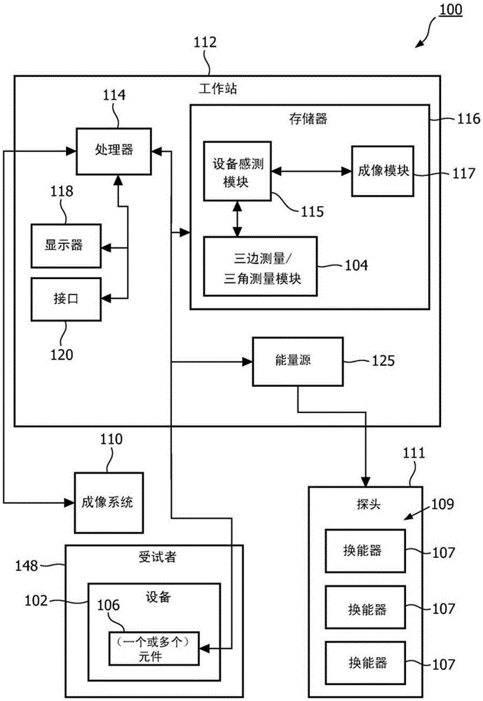
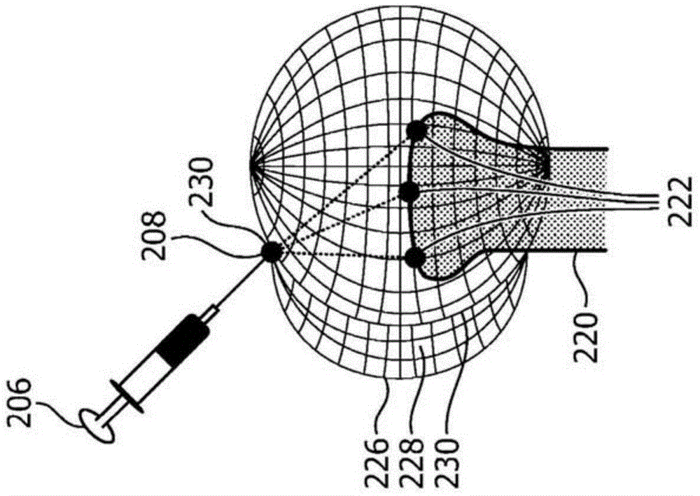
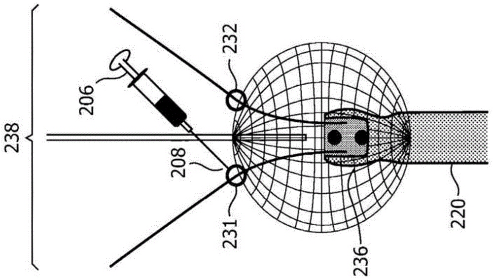
[0017] In accordance with the present principles, simultaneous imaging of the target plane, relative position, and trajectory (eg, of target anatomy relative to the target plane) of the medical device is required to avoid problems associated with losing images of out-of-plane needles during procedures. In a broad range of clinical interventions, two-dimensional (2D) visualization of the needle relative to the anatomy is achieved using a one-dimensional (1D) ultrasound probe. However, needle and tool positions cannot be assessed when they are located outside the imaging plane. The present systems and methods are provided to track and visualize out-of-plane needles without losing the target anatomy image. In one embodiment, this is accomplished using a simple one-dimensional (1D) probe (for 2D imaging) or a two-dimensional (2D) probe for 3D imaging. Also provided are methods for assessing the 3D position of a needle relative to the imaging plane using a 1D array.

[0018] Embe...


PUM


Abstract

An imaging system and method includes a medical device (102) having a tracking element (106) mounted thereon. The array of transducers (109) are spaced apart from each other to exchange energy in the subject between the tracking element and the array of transducers. The trilateration module (104) is configured to interpret signals sensed between the tracking element and the array of transducers to calculate a signal flight associated with the transducers in the array time such that the position of the tracking element is determined in at least two dimensions to locate the position of the medical device in the visual image.

Description

technical field [0001] The present disclosure relates to medical devices and procedures, and more particularly to systems and methods for localizing medical devices in three dimensions using one or two dimensional imaging probes. Background technique [0002] Needle insertion is typically performed under ultrasound guidance, eg, for biopsies, drainage, nerve blocks, vascular access, and the like. Needle visualization techniques have been successfully implemented (using eg needle visualization enhancement software) based on a directed imaging beam approximately perpendicular to the needle shaft. [0003] In a large number of cases, the needle will deviate from the imaging plane due to tissue inhomogeneity and bevel asymmetry. No matter how smart the needle visualization enhancement software is, a needle that is out of plane will disappear because the needle does not receive ultrasound energy at all. Then, the clinician must move the imaging transducer to find the needle, an...

Claims


Application Information

Patent Timeline
Patent Type & Authority Patents(China)
IPC IPC(8): A61B5/06A61B8/13
CPCA61B8/0841A61B8/4483A61B8/4494A61B8/461A61B8/466A61B8/5261A61B34/20A61B2034/2051A61B2034/2063A61B2090/3929A61B8/467A61B8/481A61B8/52
Inventor A·K·贾殷F·G·G·M·维尼翁
Owner KONINKLJIJKE PHILIPS NV
Why Eureka
Try Eureka