Polishing pad
A technique for polishing pads and light-transmitting areas, which is applied in the field of polishing pads to achieve the effects of shortening the distance, preventing the reduction of light transmittance, and improving the accuracy of optical detection
- Summary
- Abstract
- Description
- Claims
- Application Information
AI Technical Summary
Problems solved by technology
Method used
Image
Examples
preparation example Construction
[0045] There is no special limitation on the preparation method of the light-transmitting region 9, which can be prepared by known methods. For example, a method of cutting the urethane resin block prepared by the above method into a specified thickness with a slicer of a band saw type or a planer type, a method of injecting the resin into a mold having a cavity of a specified thickness and curing it, injection Mold forming method, method using coating technology or sheet forming technology.
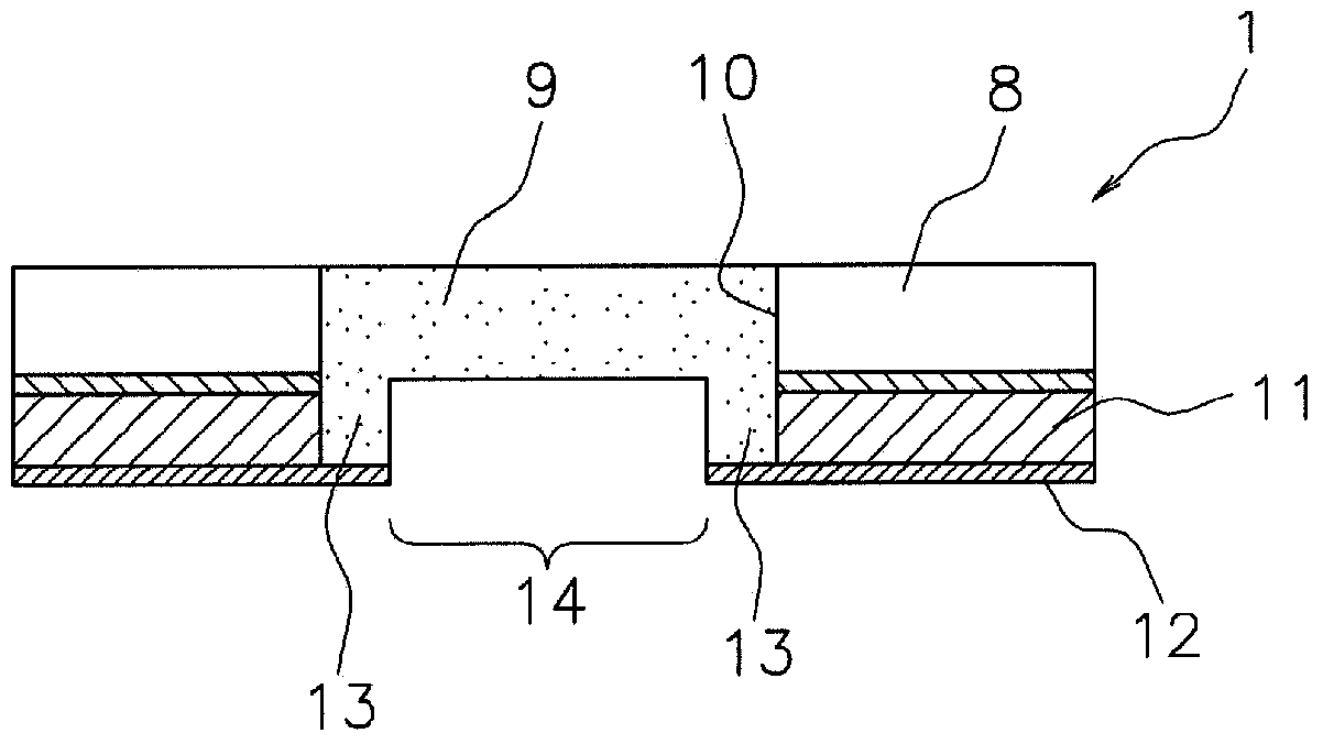
[0046] One side of the light-transmitting region 9 has a peripheral portion 13 and a recessed portion 14 . There is no particular limitation on the method of forming the depressed portion 14, for example, the method of forming by cutting the surface of the light-transmitting region prepared by the above-mentioned method, directly preparing the transparent portion with the depressed portion by injection molding method or casting molding method. method of light area, etc.
[0047] There ...
example 1
[0092] The polishing area 8 and the buffer layer 11 are adhered, and then, the opening 10 penetrating the polishing area 8 and the buffer layer 11 is formed. After that, the support film 12 is bonded to one surface of the buffer layer 11 . Next, the light-transmitting region 9 is embedded in the opening 10 , and the peripheral portion 13 of the light-transmitting region 9 is bonded to the support film 12 . In addition, the portion of the supporting film 12 corresponding to the recessed portion 14 of the light-transmitting region 9 is cut away to open the recessed portion 14 .
example 2
[0094] The polishing area 8 and the buffer layer 11 are adhered, and then, the opening 10 penetrating the polishing area 8 and the buffer layer 11 is formed. After that, the support film 12 is bonded to one surface of the buffer layer 11 . Next, a translucent resin composition is poured into the opening 10 and on the support film 12 , heated, and hardened by light irradiation or moisture to form the translucent region 9 . In addition, the supporting film 12 is cut at a portion corresponding to the depressed portion 14 of the light-transmitting region 9 , and the depressed portion 14 is formed by cutting or the like.
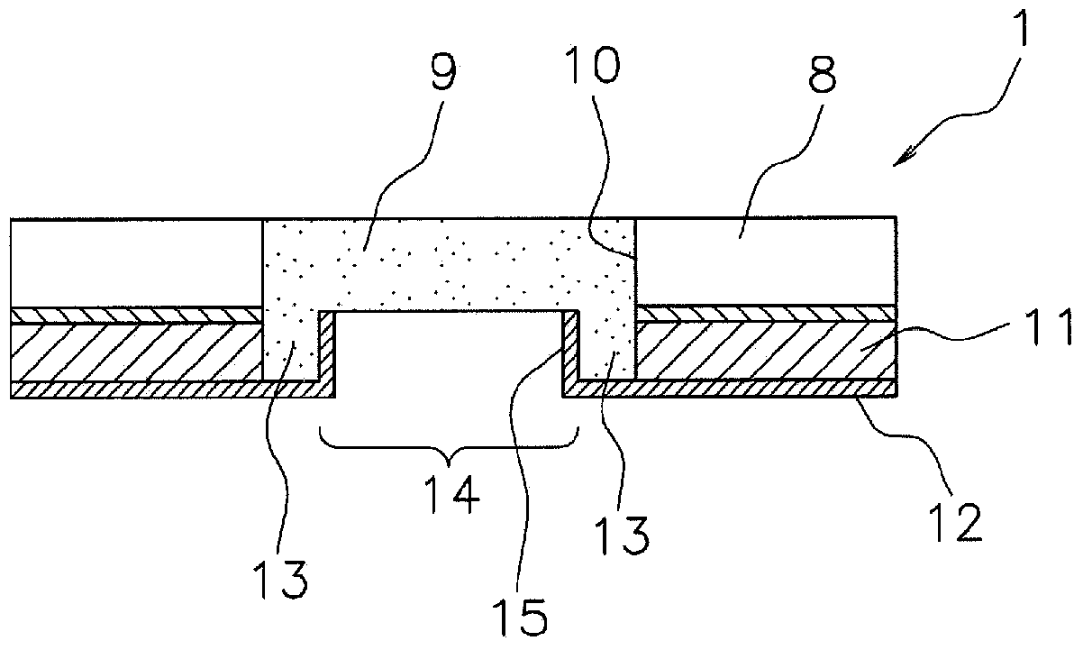
[0095] Such as image 3 As shown, the covering member 15 may be provided on the side surface of the recessed portion 14 . There are no particular limitations on the method of providing the covering member 15, and examples include a method of bonding a resin sheet, a method of applying a resin composition or an adhesive to the side of a recessed portion and curi...
PUM
 Abstract
Description
Claims
Application Information
 - R&D
- Intellectual Property
- Life Sciences
- Materials
- Tech Scout
- Unparalleled Data Quality
- Higher Quality Content
- 60% Fewer Hallucinations
Browse by: Latest US Patents, China's latest patents, Technical Efficacy Thesaurus, Application Domain, Technology Topic, Popular Technical Reports.
© 2025 PatSnap. All rights reserved.Legal|Privacy policy|Modern Slavery Act Transparency Statement|Sitemap|About US| Contact US: help@patsnap.com


