Rotary cutting tool with double cutting edge

A technology of rotating cutting tools and cutting edges, which is applied in the direction of milling cutters, manufacturing tools, metal processing equipment, etc., can solve the problems of small contribution to cutting, reduce cutting feed, and high cost of use, so as to improve cutting efficiency and reduce replacement Knife frequency and the effect of improving application ability

Active Publication Date: 2017-01-25
ZHUZHOU CEMENTED CARBIDE CUTTING TOOLS CO LTD
View PDF11 Cites 0 Cited by
  • Summary
  • Abstract
  • Description
  • Claims
  • Application Information

AI Technical Summary

Problems solved by technology

However, when the rotary cutting tool is in use, in order to ensure the smooth discharge of chips and avoid interference with the cutter body, it is necessary to have a chip space in the top surface area of ​​the milling insert in the circumferential direction, which is usually a chip pocket. To be able to provide sufficient cutting load capacity and impact resistance for the cutting insert, it is necessary to reserve a fairly thick material at the bottom of the flute. Therefore, when designing the tool, it is necessary to take into account the needs of both the chip flute and the flute. In the rotary cutting tool In the circumferential direction, there must be a large enough chip pocket for chip removal, and a sufficiently thick solid body to ensure strength, which inevitably leads to a limited number of cutting inserts
It can be seen that in the prior art, in order to improve the processing efficiency, the rotary cutting tool needs to set as many cutting blades as possible, but in order to ensure chip removal and tool strength, it needs to set as few cutting blades as possible. This contradiction has become a limitation of rotary cutting. The main factors of tool cutting performance
[0003] In order to reduce the limitation of the above-mentioned contradictions on the rotary cutting tool, a technical solution of incorporating a cutting blade with a double-layer cutting edge structure into the rotary cutting tool has emerged. The cutting blade in a sipe can be cut twice successively to achieve increased cutting. For the purpose of the number of edges, this structure greatly increases the number of effective edges that the rotary cutting tool participates in cutting. However, in order to ensure the strength of the cutting edge that first participates in cutting in the cutting blade with double-layer cutting edge structure, the cutting edge must have Sufficiently full flank face, which makes the groove space corresponding to the cutting edge participating in the cutting is very small, the groove shape design is also greatly restricted, and the corresponding chip breaking and chip holding capacity are also very poor. Therefore, for this When designing a cutting insert with a double-layer cutting edge structure, it is necessary to set the cutting radius of the cutting edge that participates in cutting relative to the central axis of rotary cutting to be smaller than the cutting radius of the cutting edge that participates in cutting first relative to the central axis of rotary cutting, so that Reduce the cutting feed corresponding to the cutting edge that participates in the cutting, so that it can produce chips that are easier to break and discharge during processing
From another point of view, since the cutting feed corresponding to the cutting edge participating in the cutting is very small, its cutting contribution is not large. In addition, the cutting blade with double-layer cutting edges has a complex structure, difficult precision control, and manufacturing The cost is very high, and when one of the two cutting edges is worn out, the entire blade must be replaced. The cost of use is very high, which shows that its cost performance is actually very low

Method used


Image

  • Rotary cutting tool with double cutting edge
  • Rotary cutting tool with double cutting edge
  • Rotary cutting tool with double cutting edge

Examples


Embodiment Construction

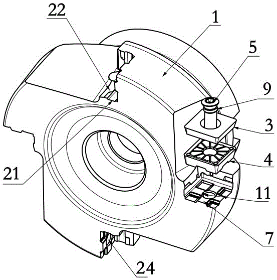
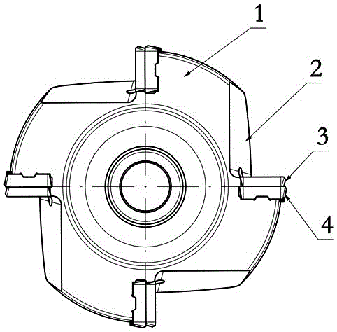
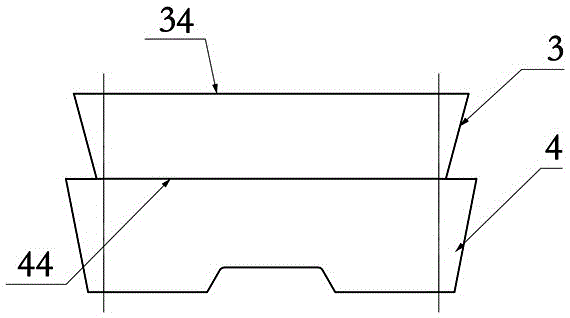
[0037] Figure 1 to Figure 7Shown is the first embodiment of the rotary cutting tool with double-layer cutting edge of the present invention, the rotary cutting tool includes a cutter body 1, at least one set of sipes 2 are arranged on the cutter body 1, and the slits 2 are fastened The part 5 is fixed with a cutting blade group consisting of a first cutting blade 3 and a second cutting blade 4, the first cutting blade 3 is pressed on the second cutting blade 4, and the second cutting blade 4 is pressed on the sipe 2, The second cutting blade 4 has a larger rotational cutting radius than the first cutting blade 3. During cutting, the cutting feed of the second cutting blade 4 is greater than or equal to the cutting feed of the first cutting blade 3. In a single sipe There are superposed first cutting blades 3 and second cutting blades 4, the two blades are independent of each other, and can be processed separately during processing, and the design restrictions on the respectiv...


PUM


Abstract

The invention discloses a rotary cutting tool with a double-layered cutting edge. The rotary cutting tool comprises a tool body, the tool body is provided with at least one set of tool grooves, a cutting tip set consisting of a first cutting tip and a second cutting tip is fixed on each tool groove by a fastener, the first cutting tip is pressed on the second cutting tip, the second cutting tip is pressed on the tool groove, and in the process of cutting processing, the cutting feed of the second cutting tip is larger than or equal to that of the first cutting tip. The rotary cutting tool with a double-layered cutting edge disclosed by the invention has the advantages of high cutting efficiency, easy manufacturing, cost reduction and smooth chip removal.

Description

technical field [0001] The invention relates to the field of metal cutting, in particular to a rotary cutting tool with double-layer cutting edges. Background technique [0002] In order to improve the machining efficiency, the rotary cutting tool is usually equipped with as many cutting inserts as possible, so as to set as many cutting edges as possible for the rotary cutting tool. The purpose of this is to minimize the cutting on the cutting insert under the same feed. Forces especially tangential forces. However, when the rotary cutting tool is in use, in order to ensure the smooth discharge of chips and avoid interference with the cutter body, it is necessary to have a chip space in the top surface area of ​​the milling insert in the circumferential direction, which is usually a chip pocket. To be able to provide sufficient cutting load capacity and impact resistance for the cutting insert, it is necessary to reserve a fairly thick material at the bottom of the flute. T...

Claims


Application Information

Patent Timeline
Patent Type & Authority Patents(China)
IPC IPC(8): B23C5/20
Inventor 江爱胜
Owner ZHUZHOU CEMENTED CARBIDE CUTTING TOOLS CO LTD
Why Eureka
Try Eureka