A roll removal device

A technology of dismantling device and roll, applied in the direction of metal rolling, metal rolling, metal rolling stand, etc., can solve the problems of increasing the consumption of spare parts, the difficulty of lifting heavy parts by crane, and the difficulty of dismantling, etc. Improve operation efficiency and equipment operation rate, reduce spare parts consumption and expenses, and reduce labor intensity

Active Publication Date: 2016-03-02
ANGANG STEEL CO LTD
View PDF6 Cites 0 Cited by
  • Summary
  • Abstract
  • Description
  • Claims
  • Application Information

AI Technical Summary

Problems solved by technology

[0002] In the continuous rolling production line of the hot rolling mill, it is very difficult to replace the rolls or the conveying roller table. The roller table bearing needs to disassemble the gear first. Since the gear is installed in a hot-loading method, it is used to match the conveying roller shaft. If the gear is cut off, it will increase the consumption of spare parts. After being heated by gas welding, the disassembly of the gear with a sledgehammer is not only time-consuming and laborious, but also poses a great safety hazard.
Especially for the disassembly of heavy rolls and bearing housings, it is even more difficult. It is difficult to lift heavy parts by crane, it is not easy to fix, and it requires a lot of force to disassemble. It is difficult to disassemble without using powerful tools. , due to the low efficiency of disassembly, it seriously affects the smooth progress of production

Method used


Image

  • A roll removal device
  • A roll removal device
  • A roll removal device

Examples


Embodiment Construction

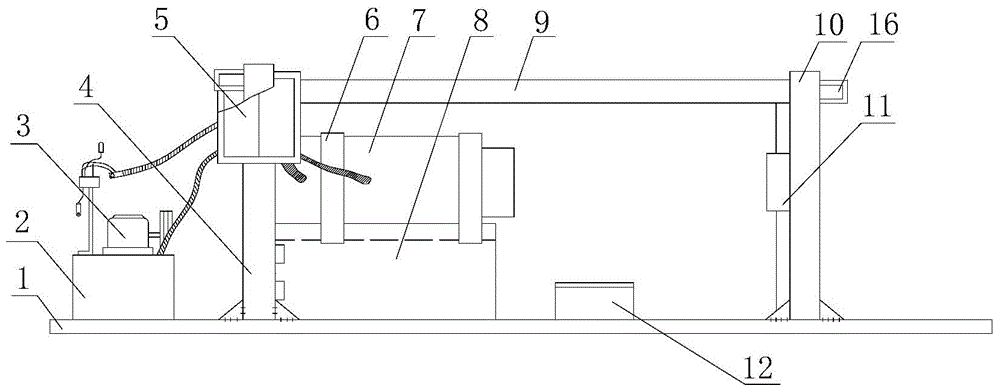
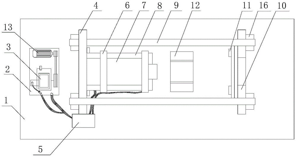
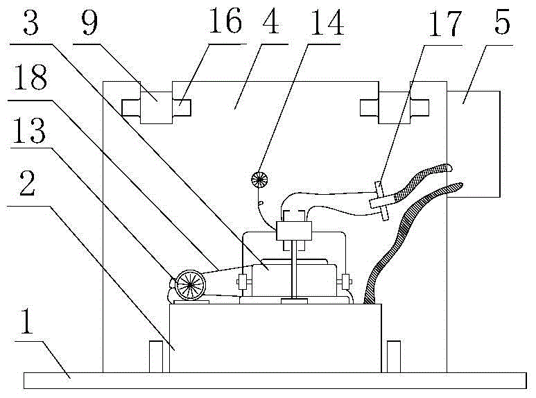
[0016] As can be seen from the accompanying drawings, the present invention is mainly composed of a base 1, a gear pump 3, a pallet 4, an electric control box 5, a clamp hoop 6, a support 8, a pull rod 9, a deck 10, an iron stop 11, a pad iron 12, a motor 13. It is composed of wedge iron 16, belt 18 and hydraulic system. The hydraulic system includes a fuel tank 2, a gear pump 3, a hydraulic cylinder 7, a pressure gauge 14, a manifold 15, an oil filter 17 and a reversing valve.

[0017] On the left side upper surface of the base 1, a card plate 4 is vertically welded, and a card holder 10 is vertically welded on the right upper surface, and a card slot is respectively opened on both sides of the upper end of the card plate 4 and the card holder 10, and the two pull rods 9 The end is clamped in the slot and fixed by wedge iron 16. The inner side of the clamping plate 4 is connected with a "V"-shaped support 8 by bolts, and a hydraulic cylinder 7 is fixed through the clamp 6 in...


PUM


Abstract

The invention provides a roller detaching device which comprises a base, a motor, an electric cabinet, clamping plates, a clamping base, a support, a pull rod, a sizing block, stop iron, a clamping hoop, an oil tank, a gear pump, a hydraulic cylinder, an integrated block, an oil filter and a pressure gauge. Clamping grooves are formed in the clamping plates on two sides of the base and the upper end of the clamping base, the two ends of the pull rod are fixed in the clamping grooves through wedges, the hydraulic tank is fixed on the support on the inner sides of the clamping plates, the hydraulic tank is connected with the gear pump, the gear pump and the motor are fixed on the oil tank, the electric cabinet is arranged on the clamping plates, the electric cabinet is connected with the motor and the integrated block, and the motor is connected with the gear pump through a belt. A bearing seat to be detached is hung on the sizing block, namely the roller or a conveying roller shaft can be ejected out from the bearing seat through a hydraulic cylinder piston rod. By means of the device, the roller and the bearing seat or the gear and the roller shaft can be detached and separated fast, detaching time is shortened, labor intensity is reduced, the detached part is prevented from being damaged, spare part consumption is reduced, safety accidents are avoided, and device operation rate is improved.

Description

technical field [0001] The invention belongs to the field of mechanical equipment, in particular to a roller shaft dismounting device for rollers or conveying roller tables. Background technique [0002] In the continuous rolling production line of the hot rolling mill, it is very difficult to replace the rolls or the conveying roller table. The roller table bearing needs to disassemble the gear first. Since the gear is installed in a hot-loading method, it is used to match the conveying roller shaft. If the gear is cut off, it will increase the consumption of spare parts. After being heated by gas welding, the disassembly of the gear with a sledgehammer is not only time-consuming and laborious, but also poses a great safety hazard. Especially for the disassembly of heavy rolls and bearing housings, it is even more difficult. It is difficult to lift heavy parts by crane, it is not easy to fix, and it requires a lot of force to disassemble. It is difficult to disassemble with...

Claims


Application Information

Patent Timeline
Patent Type & Authority Patents(China)
IPC IPC(8): B23P19/027B21B31/08
CPCB21B31/08B23P19/025B23P19/027
Inventor 高峰
Owner ANGANG STEEL CO LTD
Why Eureka
Try Eureka