Push rod capable of exhausting

An exhaust push rod and exhaust groove technology, which is applied in the field of exhaustable push rods, can solve the problems affecting the molding quality of products and the injection molding cycle, reducing the melt filling speed, and increasing the injection pressure, so as to improve the injection molding production efficiency. , the effect of ensuring quality and reducing energy consumption

Inactive Publication Date: 2014-04-30
SUZHOU VOCATIONAL UNIV
View PDF3 Cites 2 Cited by
  • Summary
  • Abstract
  • Description
  • Claims
  • Application Information

AI Technical Summary

Problems solved by technology

The injection mold belongs to the cavity mold. In injection molding, the moisture in the plastic evaporates at high temperature or the plastic additives decompose to form gas at high temperature, and the residual air in the cavity itself after mold closing will cause a large amount of air to accumulate in the mold cavity. When the plastic melt enters the cavity quickly for injection molding, these gases need to be discharged in time, otherwise the product will be partially carbonized and scorched due to the high temperature generated by the compression of the gas; or the injection pressure will increase due to the failure of the gas to be discharged in time, resulting in In addition, if the gas cannot be discharged in time, the pressure in the cavity and the resistance of the melt to advance will increase, and eventually the filling speed of the melt will be reduced or defects such as insufficient filling will occur. Factors will ultimately affect the molding quality and injection molding cycle of the product, such as the formation of flow marks, air marks, weld lines, partial filling and dissatisfaction on the surface of the product, and even local flashing or local carbonization of the product.

Method used


Image

  • Push rod capable of exhausting
  • Push rod capable of exhausting
  • Push rod capable of exhausting

Examples


Embodiment Construction

[0013] The present invention is described below in conjunction with accompanying drawing.

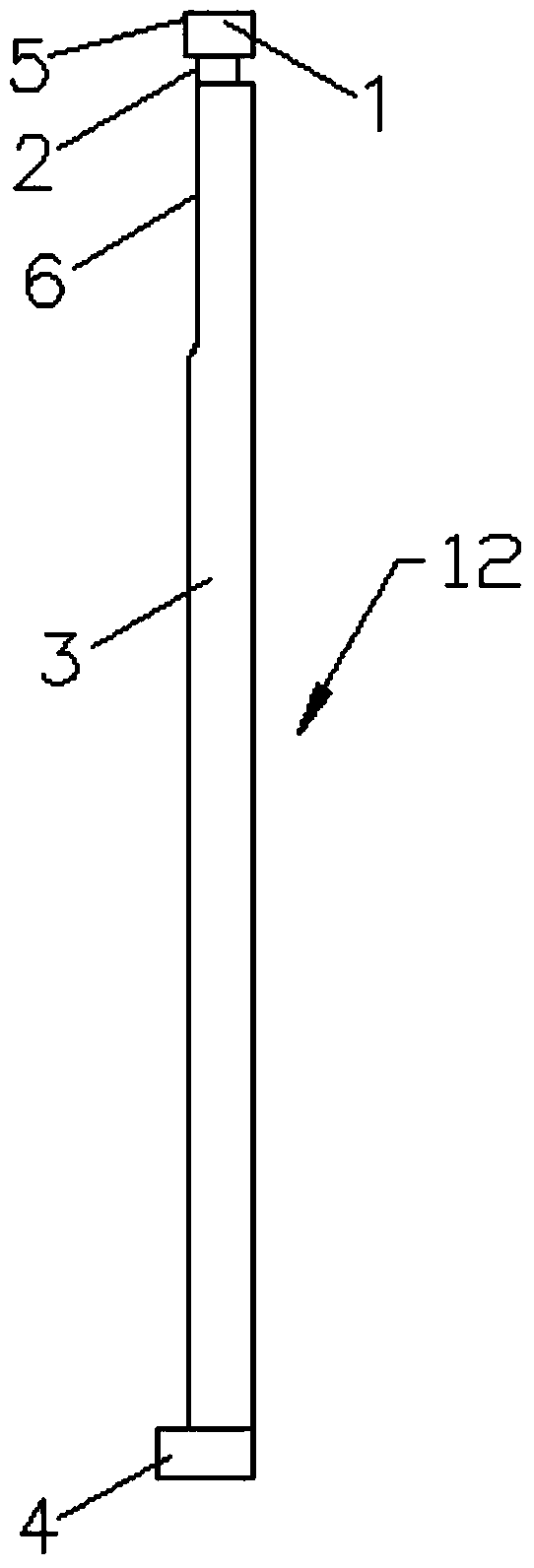
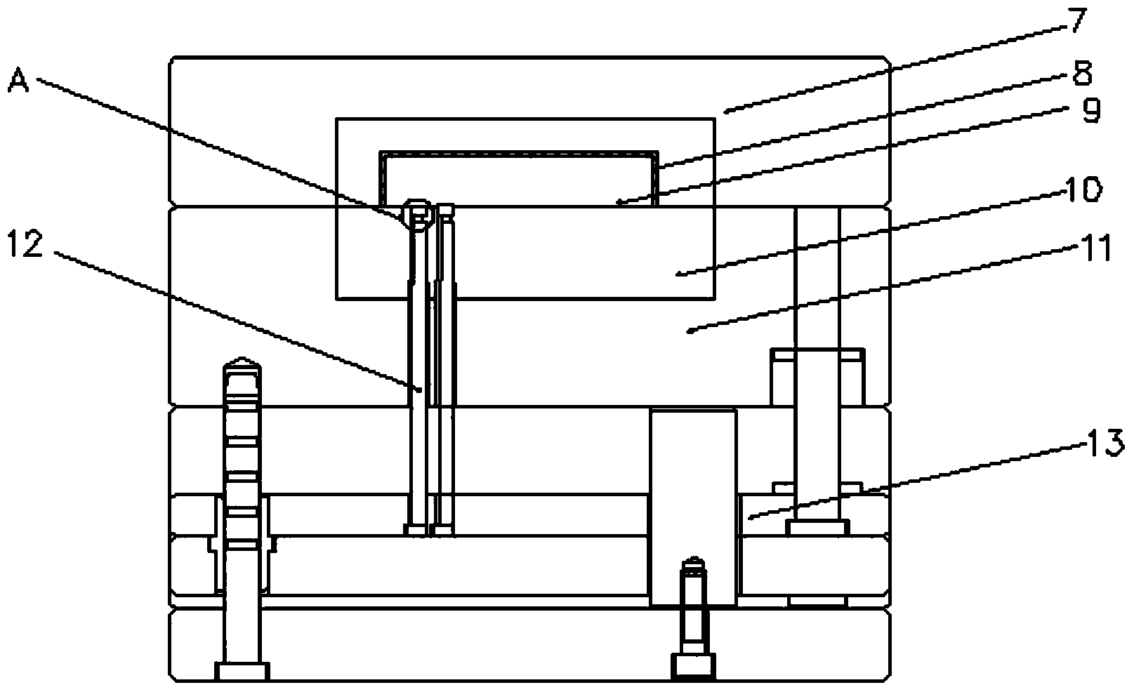
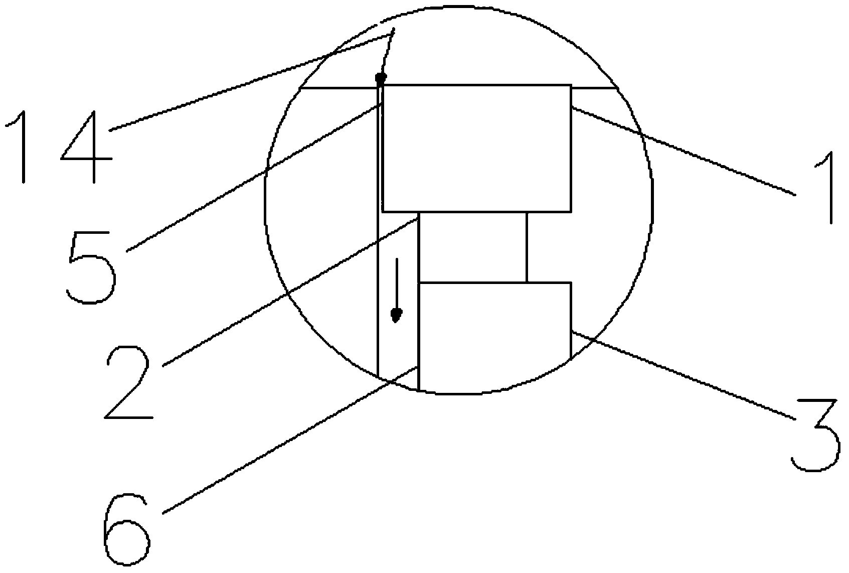
[0014] as attached Figure 1-3 Shown is the exhaustable push rod of the present invention, including a push rod head 1, a knife relief groove 2, a rod body 3, and a hanging platform 4; the lower end of the push rod head 1 is provided with a knife relief groove 2; A rod body 3 is arranged under the groove 2; a hanging platform 4 is arranged at the bottom end of the rod body 3; an upper exhaust groove 5 is provided on one side of the push rod head 1; the rod body on the same side of the upper exhaust groove 5 3 is provided with a side exhaust groove 6, the side exhaust groove 6 is on the same side as the upper exhaust groove 5, and the side surface of the side exhaust groove 6 is flush with the undercut groove 2; The hanging platform 4 on the same side of the side exhaust groove 6 is provided with a protruding shoulder, and the other side of the hanging platform 4 is flush with the rod b...


PUM


Abstract

The invention discloses a push rod capable of exhausting. The push rod comprises a push rod head, a tool withdrawal groove, a rod body and a suspension table, wherein the tool withdrawal groove is formed in the lower end of the push rod head; the rod body is arranged below the tool withdrawal groove; the suspension table is arranged at the bottom end of the rod body; an upper exhausting groove is formed in one side of the push rod head; a lateral exhausting groove is formed in the rod body; the lateral exhausting groove and the upper exhausting groove are formed in the same side; the lateral surface of the lateral exhausting groove is levelly connected with the tool withdrawal groove in parallel; a convex shoulder is arranged on the suspension table on the same side of the lateral exhausting groove in the rod body; the other side of the suspension table is level and parallel to the rod body without any convex shoulder. The push rod provided by the invention has the advantages of simple structure and convenience in repairing and assembling, so that the quality of a modeling product can be ensured; meanwhile, the modeling period can be shortened; energy consumed by an injector can be reduced; the production efficiency of injection molding is greatly improved.

Description

technical field [0001] The invention relates to an exhaustable push rod which can discharge gas in a mold cavity in time during injection production to ensure product quality. Background technique [0002] Injection mold is an important process equipment in plastic injection production. The injection mold belongs to the cavity mold. In injection molding, the moisture in the plastic evaporates at high temperature or the plastic additives decompose to form gas at high temperature, and the residual air in the cavity itself after mold closing will cause a large amount of air to accumulate in the mold cavity. When the plastic melt enters the cavity quickly for injection molding, these gases need to be discharged in time, otherwise the product will be partially carbonized and scorched due to the high temperature generated by the compression of the gas; or the injection pressure will increase due to the failure of the gas to be discharged in time, resulting in In addition, if the ...

Claims


Application Information

Patent Timeline
Patent Type & Authority Applications(China)
IPC IPC(8): B29C45/34
CPCB29C45/34
Inventor 李耀辉
Owner SUZHOU VOCATIONAL UNIV
Why Eureka
Try Eureka