Automatic transporting and packing system

A technology of automatic transportation and driven shaft, applied in transportation and packaging, conveyors, conveyor objects, etc., can solve the problems of waste of human and land resources, low labor efficiency, occupation of land resources, etc., to achieve less space occupation and production. Powerful, easy-to-use effects

Active Publication Date: 2014-04-30
SHANDONG HENGXIANG MACHINERY
8 Cites 6 Cited by

AI-Extracted Technical Summary

Problems solved by technology

[0002] At present, the handling and packing process of bricks or finished products is mainly done manually, which not only takes up a lot of labor, but ...

Abstract

The invention relates to a green brick transportation system, in particular to an automatic transporting and packing system. The automatic transporting and packing system comprises a frame. A first synchronous belt, a second synchronous belt, an overturning mechanism, a brick retaining frame, a brick dividing frame and a broad conveying belt are all arranged on the frame in sequence. Two travelling trolleys are arranged above the frame; after led to the first synchronous belt, green bricks are conveyed to the overturning mechanism and driven to rotate by 90 degrees through the overturning mechanism and reach a workbench under cooperation of the traveling trolleys, the brick retaining frame, the brick dividing frame and the broad conveying belt, and automatic packing can be fulfilled through a robot. The automatic transporting and packing system is simple in structure and operation, high in adaptability, low in dependence on labor, large in production capacity and high in efficiency.

Application Domain

Stacking articlesDe-stacking articles +2

Technology Topic

Transit systemMechanical engineering +3

Image

  • Automatic transporting and packing system
  • Automatic transporting and packing system
  • Automatic transporting and packing system

Examples

  • Experimental program(1)

Example Embodiment

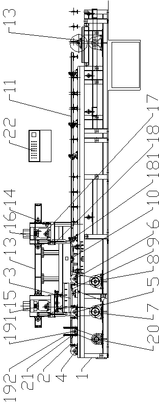
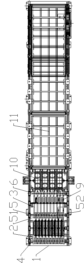
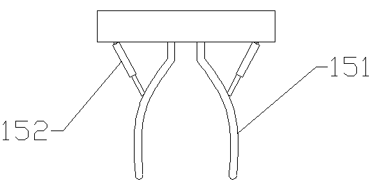
[0021] Accompanying drawing is the specific embodiment of the present invention. like Figure 1 to Figure 6 As shown, this kind of automatic transportation and coding system includes a frame 1, and several first synchronous belts 2 are arranged at the head end of the frame 1 along the length direction of the frame 1, and the head end and the end of the first synchronous belt 2 are respectively Winding on the first driven shaft 4 and several driving wheels 51, these several driving wheels 51 are fixed on the driving shaft 5 and are at certain intervals, as Image 6 As shown, a driven wheel 52 is provided between adjacent two driving wheels 51, and the driven wheel 52 can rotate on the driving shaft 5 through a bearing. The front of the driving shaft 5 is provided with a second driven shaft 6, and the second synchronous belt The head end and the end of 3 are respectively wound on the above-mentioned several driven wheels 52 and the second driven shaft 6, the driving shaft 5 is connected with the first transmission motor 7, the first transmission motor 7 drives the driving shaft 5 to rotate, and the driving wheels 51 are synchronized Rotate, then drive the first synchronous belt 2 to rotate, the second driven shaft 6 is connected with the second transmission motor 8, the second transmission motor 8 drives the second driven shaft 6 to rotate, and then drives the second synchronous belt 3 to rotate. The rear of the two driven shafts 6 is provided with a blank frame 9, and the front of the second driven shaft 6 is successively provided with a blank frame 10 and a conveyor belt 11, and the conveyor belt 11 is driven by the third transmission motor 12 to rotate; A slide rail 13 is provided above, and two pulleys 14 are arranged successively along the length direction of the frame 1 on the slide rail 13, and the first traveling trolley 15 and the second traveling trolley 16 are respectively connected below the two pulleys 14, and the first traveling trolley 15 and the second walking trolley 16 all include the fourth transmission motor 17 in the vertical direction, the fourth transmission motor 17 is connected with the pulley 14 through the speed changer, and drives the pulley 14 to slide back and forth, and the fourth transmission motor 17 rear is provided with two along the frame 1 The blank blocking cylinder 18 arranged horizontally and with the output end downward, the output end of the blank blocking cylinder 18 is provided with a blank pushing plate 181, and the front of the fourth transmission motor 17 of the first traveling trolley 15 is provided with a clamp for arranging bricks Blank holder 151, such as image 3 As shown, the blank folder 151 is arranged along the length direction of the frame 1, and the two sides of the blank folder 151 are respectively hinged to control the cylinder 152; a turning mechanism is also provided behind the driving shaft 5, and the turning mechanism is driven by the frequency conversion automatic motor 20 to turn over. like Figure 4 , Figure 5 As shown, the overturning mechanism includes a rotating shaft 191, and the rotating shaft 191 is provided with a set of overturning components located between the two first synchronous belts 2. The overturning component includes four right-angled plates 192 that are evenly distributed in a well shape along the axis of the rotating shaft 191, The turning assembly turns over 90° each time, and the horizontal part of the upper right-angle plate 192 after turning over is flush with the first synchronous belt 2, and a photoelectric switch 21 is arranged at the right angle of the right-angle plate 192 in the upper left corner of the turning assembly, and a frequency conversion automatic motor 20 , photoelectric switch 21, control cylinder 152, the first transmission motor 7, the second transmission motor 8, the third transmission motor 12, the fourth transmission motor 17 and the blank cylinder 18 are all connected with the control cabinet 22.
[0022] The working process is as follows: After the bricks are pushed out from the cutting table to reach the specified number, they are guided to the first synchronous belt 2 by the guide mechanism driven by the guide motor, and the first synchronous belt 2 drags the bricks to move forward and reach the right-angle plate 192 of the turning mechanism. At the right angle to the right angle, the photoelectric switch 21 captures the signal and transmits it to the control cabinet 22, the automatic frequency conversion motor turns forward 90°, turns the adobe onto the second synchronous belt 3, and the second transmission motor 8 starts to drive the adobe forward evenly Conveying, when the number of bricks reaches a certain amount, the blank block frame 9 is lifted, and the rear bricks are suspended for conveying. At this time, the output of the cylinder 152 is controlled, and the clamp 151 is clamped to tidy the bricks. Then the cylinder 152 is controlled to retract, and the clamping folder 151 releases the adobe, the adobe block cylinder 18 outputs downwards, the fourth transmission motor 17 on the first traveling trolley 15 starts, drives the first traveling trolley 15 to move forward, and simultaneously pushes the adobe 181 to push the adobe into batches. , the first walking trolley 15 returns; the adobe realizes left and right splitting on the dividing rack 10, and then the fourth transmission motor 17 on the second traveling trolley 16 is started, and the blank blocking cylinder 18 is output downward at the same time, and the blank pushing plate 181 pushes the adobe Continue to move forward until the conveying belt 11 is on and then return, the conveying belt 11 continues to convey the adobes, and then the robot completes the adobe stacking work, and a conveying cycle is completed. In this cycle, the adobes are automatically stacked into piles.
[0023] Except for the technical features described in the description, the rest of the technical features are known to those skilled in the art.

PUM

no PUM

Description & Claims & Application Information

We can also present the details of the Description, Claims and Application information to help users get a comprehensive understanding of the technical details of the patent, such as background art, summary of invention, brief description of drawings, description of embodiments, and other original content. On the other hand, users can also determine the specific scope of protection of the technology through the list of claims; as well as understand the changes in the life cycle of the technology with the presentation of the patent timeline. Login to view more.

Similar technology patents

Betel nut packing machine

ActiveCN105270678ASmall footprintreduce noise
Owner:KUNSHAN BAIAO INTELLIGENT EQUIP CO LTD

Support frame of adjustable suspension scaffold

Owner:江苏金土木建设集团华顺工程有限公司

Portable wetlands

InactiveUS20080179240A1high surface areasmall footprint
Owner:KAUPPI FREDERICK J +2

Classification and recommendation of technical efficacy words

  • small footprint
  • adaptable

ROS based service robot and indoor navigation method thereof

Owner:北京海风智能科技有限责任公司

Measuring system of three-dimensional shape of strong reflecting surface based on high dynamic strip projector

ActiveCN102937425AadaptableOvercome the influence of background light on measurement
Owner:BEIHANG UNIV

Production method of low-cost X52 pipeline steel and pipeline steel

ActiveCN103572025ASimple production process controladaptable
Owner:攀钢集团西昌钢钒有限公司 +1
Why Eureka
Try Eureka