Large-volume anti-deformation steel reinforcement cage and binding method thereof

A steel cage, anti-deformation technology, applied in artificial islands, structural elements, building components, etc., can solve problems such as large self-weight deformation, large structural size and weight of steel cages, and difficulty in meeting design and construction requirements. High, improve the overall binding quality, and ensure the effect of binding quality

Active Publication Date: 2014-04-30
CCCC SECOND HARBOR ENG +3
View PDF3 Cites 1 Cited by
  • Summary
  • Abstract
  • Description
  • Claims
  • Application Information

AI Technical Summary

Problems solved by technology

With the development of immersed tube prefabrication construction technology, for super-large subsea tunnel steel cage prefabrication project, the traditional reinforcement method has been difficult to meet the design and construction requirements
The main reasons are: (1) The structural size and weight of the steel cage are large, and the deformation caused by its own weight is relatively large; (2) The steel cage is bound in three sections of flowing water; The bottom plate reinforcement is pushed into the wall binding area to bind the wall reinforcement, and then pushed into the roof reinforcement binding area to bind the roof reinforcement, and finally pushed into the pouring area for concrete pouring; it is necessary to ensure that the reinforcement cage is basically maintained during the moving process. No deformation; but the current steel cage binding process can not achieve the above two points

Method used


Image

  • Large-volume anti-deformation steel reinforcement cage and binding method thereof
  • Large-volume anti-deformation steel reinforcement cage and binding method thereof
  • Large-volume anti-deformation steel reinforcement cage and binding method thereof

Examples


Embodiment Construction

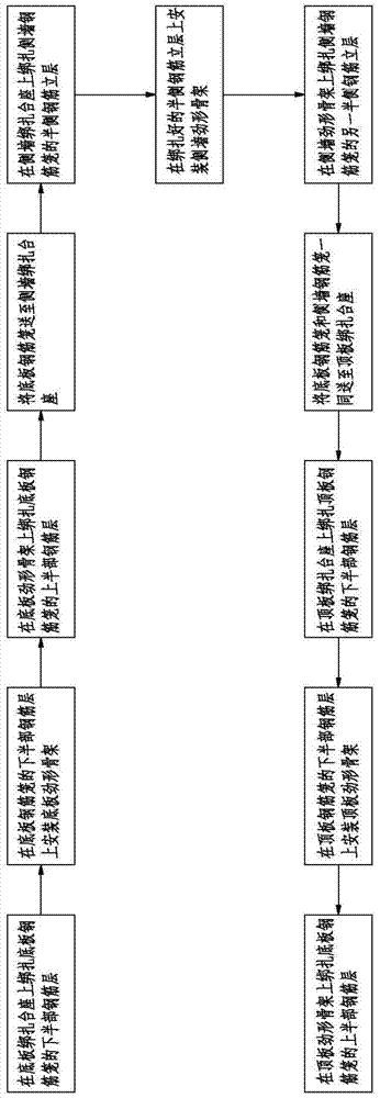
[0034] see figure 1 (the direction of the arrow is the pushing direction of the reinforcement cage), a kind of large-volume deformation-resistant reinforcement cage binding method of the present invention comprises the following steps:

[0035] 1. Bind the lower half of the steel reinforcement cage of the bottom plate on the bottom plate binding pedestal;

[0036] 2. Vertically install the stiff-shaped skeleton of the bottom plate on the lower half of the reinforcement layer of the bound bottom plate reinforcement cage;

[0037] 3. Bind the upper half of the steel bar layer of the bottom plate reinforcement cage on the stiff frame of the bottom plate. So far, the lower half of the steel bar layer is combined with the upper half of the steel bar layer to form a bottom plate reinforcement cage; and the bottom plate reinforcement cage is formed through the bottom plate stiff frame inner support. In this embodiment, the stiff frame of the bottom plate includes a plurality of bot...


PUM


Abstract

The invention relates to a large-volume anti-deformation steel reinforcement cage and a binding method thereof. The binding method comprises the following steps: binding the lower half steel-bar layer of a base-plate steel reinforcement cage to a base-plate binding pedestal; installing a base-plate stiff skeleton on the lower half steel-bar layer of the base-plate steel reinforcement cage; binding the upper half steel-bar layer of the base-plate steel reinforcement cage to the base-plate stiff skeleton; sending the base-plate steel reinforcement cage to a side-wall binding pedestal; binding the half-side steel-bar vertical layer of a side-wall steel reinforcement cage to the side-wall binding pedestal; installing a side-wall stiff skeleton to the bound half-side steel-bar vertical layer; binding another half-side steel-bar vertical layer of the side-wall steel reinforcement cage to the side-wall stiff skeleton; sending the base-plate steel reinforcement cage and the side-wall steel reinforcement cage to a top-plate binding pedestal together; binding the lower half steel-bar layer of a top-plate steel reinforcement cage to the top-plate binding pedestal; installing a top-plate stiff skeleton on the lower half steel-bar layer of the top-plate steel reinforcement cage; and binding the upper half steel-bar layer of the base-plate steel reinforcement cage to the top-plate stiff skeleton, so as to form the top-plate steel reinforcement cage.

Description

technical field [0001] The invention relates to a large-volume anti-deformation reinforcement cage and a binding method thereof, in particular to a method of separately installing a bottom plate reinforcement cage, a side wall reinforcement cage and a roof reinforcement cage in the binding process of a bottom plate reinforcement cage and a side wall reinforcement cage. A large-volume anti-deformation reinforcement cage and a binding method thereof for realizing stage-by-stage binding of the deformation-resistant reinforcement cage by using a stiff-shaped skeleton on the top plate. Background technique [0002] At present, large-scale reinforced concrete members that are common in China rarely use large-scale skeletons as members supported by steel cages, and most of them only add reinforcing ribs locally to ensure that the steel cages do not deform. With the development of immersed tube prefabrication construction technology, for super-large subsea tunnel steel cage prefabri...

Claims


Application Information

Patent Timeline
Patent Type & Authority Applications(China)
IPC IPC(8): E04C5/06E02D29/07B28B21/56
Inventor 周光强翟世鸿张洪刘经国苏怀平林鸣尹海卿刘然杨红李诗明李阳杨绍斌孟庆龙
Owner CCCC SECOND HARBOR ENG
Why Eureka
Try Eureka