
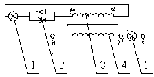
Transient impedance transformer based on alternating current voltage regulating electronic switch

A technology of impedance transformer and AC voltage regulation, which is applied in the direction of AC network circuit, AC network voltage adjustment, constant current power supply AC circuit, etc., and can solve the problem of small application range of series voltage regulation transformer, intermittent voltage waveform and excessive harmonics , Transformer switch response speed is slow and other problems, to achieve the effect of easy equipment automation, reduce voltage fluctuation and flicker, and realize equipment automation

Active Publication Date: 2014-04-30
孙崇山
View PDF3 Cites 21 Cited by
  • Summary
  • Abstract
  • Description
  • Claims
  • Application Information

AI Technical Summary

Problems solved by technology

[0054] One of the objectives of the present invention: to solve the problems of intermittent voltage waveform and excessive harmonics, small control capacity and low voltage level when the AC voltage regulator regulates voltage
[0055] The second purpose of the present invention is to solve the problems of slow response speed, short service life and arc discharge of current transformer switches
[0056] The third purpose of the present invention: to solve the problem of small application range of traditional series voltage regulating transformers

Method used


Image

  • Transient impedance transformer based on alternating current voltage regulating electronic switch
  • Transient impedance transformer based on alternating current voltage regulating electronic switch
  • Transient impedance transformer based on alternating current voltage regulating electronic switch

Examples


example 1

[0184] This scheme does not use the AC voltage regulating electronic switch, but uses a new type of AC voltage regulator, mainly to show the voltage regulation ability of the AC voltage regulator in an extreme situation. One electric furnace with resistive and inductive load. When the distance between the electrode and the material surface of the electric furnace is determined, the maximum output voltage of the series transformer is 1, and the minimum output voltage is 0.7.

[0185] One set of electric furnace transformer, three-phase, series voltage regulating transformer, voltage regulation range 30%, positive voltage regulation, main series transformer are all Yd11 connection groups. Then the low voltage output constant voltage of the main transformer is U1=0.7, and the highest output voltage of the low voltage series transformer is U2=0.3. The high-voltage voltage and current of the series transformer can be freely combined, and only need to be equal to the capacity of the...

example 2

[0195] An electric furnace transformer with a voltage regulation range of 40%, positive and negative voltage regulation, Yd11 connection group, and a series voltage regulation transformer.

[0196] The secondary winding of the main transformer is connected in parallel with the capacitor bank to adjust the power factor, before compensation , after claiming compensation .

[0197] For the principle of electrical wiring, see the combination form of low-voltage winding and reactive power compensation device, see Figure 16 .

[0198] u 21 , U 22 The main transformer and the secondary voltage of the series transformer respectively, and the leakage reactance of the transformer is ignored.

[0199] The current vector diagram before compensation is Figure 17 .

[0200] The pre-compensation power factor is:

[0201] At the same time, set the working current I of the electric furnace L = 1

[0202] In this way, the active component I of the operating current R = 0.8

...

example 3

[0225] Example 3: An electric furnace transformer with a voltage regulation range of 40%, positive and negative voltage regulation, Yd11 connection group, and a series voltage regulation transformer. Main transformer low voltage voltage=0.8, series transformer low voltage voltage 0~0.2, main series transformer composite voltage=0.8±(0~0.2), 21 levels of voltage regulation, each level voltage 0.02, main transformer capacity 0.4~1, main transformer capacity of each level The difference is 0.03. Set the transformation ratio to 1, and the high and low voltage resistances are equal. Suppose the operating current in the electric furnace after compensation is still I L =1, the current of the secondary winding of the main transformer becomes I 21 =0.842 , the no-load loss accounts for 15% of the load loss.

[0226] It can be seen from Example 1 that the transformer loss Pk is

[0227] Pk=(0.842I L ) 2 ×0.8×R+ (I L ) 2 ×0.2×R=((0.842 ) 2 ×0.8 +0.2)×(I L ) 2 ×R=0.767(I L...


PUM


Abstract

The invention elaborates on the waveform addition principle based on waveform continuity and harmonic wave viewpoint, discloses three concepts of flexible alternating current transformation, flexible power transmission and transformation and flexible voltage regulation, discloses three new technologies of the transient impedance technology, the flexible stipples voltage regulating technology and the flexible stepped voltage regulating technology, and discloses three new products of an alternating current voltage regulating electronic switch, a transient impedance transformer and a high speed voltage regulating transformer, and discloses six high-voltage power grid connection methods of a high-voltage power grid connection method for the transient impedance transformer type, a high-voltage power grid connection method for the transient impedance boosting self-coupling transformer type and the like. The novel reactive compensation connection method is provided, so that a reactive compensation device can be in series connection and parallel connection at the port of a secondary outgoing wire of a main transformer of a series voltage regulating transformer. The transient impedance transformer based the alternating current voltage regulating electronic switch can be applied to high voltage, super high voltage alternating and direct current power transmission and other systems needing to be safely, efficiently and synchronously controlled and systems needing large capacity stepless voltage regulation.

Description

technical field [0001] This paper expounds in detail the expansion of a principle, and puts forward three concepts, three new technologies, three new products, six high-voltage grid connection methods, a new reactive power compensation connection method, and the use of AC voltage regulators. A brand-new solution is proposed, involving fields such as power electronics, transformers, high-voltage and ultra-high-voltage power grid transmission, stepless voltage regulation technology, and reactive power compensation technology. [0002] An extension of the principle is the principle of waveform superposition based on the viewpoint of continuous waveform and flexible substation. [0003] The three concepts are flexible AC power transformation, flexible power transmission and transformation, and flexible voltage regulation. [0004] The three new technologies are transient impedance technology, flexible stepless voltage regulation technology and flexible stepless voltage regulation...

Claims


Application Information

Patent Timeline
Patent Type & Authority Applications(China)
IPC IPC(8): H02J3/12H02J3/18
CPCY02E40/30H02J3/36Y02E60/60H02J3/1878H02J3/12H02P13/06H02J50/10H02J3/10
Inventor 孙崇山
Owner 孙崇山
Learn More