
Method for positioning bioluminescence imaging light sources in small animal

A bioluminescence, positioning method technology, applied in medical science, sensors, diagnostic recording/measurement, etc., can solve problems such as inaccurate positioning and reconstruction errors

Inactive Publication Date: 2014-05-07
XIDIAN UNIV
View PDF13 Cites 4 Cited by
  • Summary
  • Abstract
  • Description
  • Claims
  • Application Information

AI Technical Summary

Problems solved by technology

due to l 0 The norm is approximated, which will inevitably introduce reconstruction errors, resulting in inaccurate positioning

Method used


Image

  • Method for positioning bioluminescence imaging light sources in small animal
  • Method for positioning bioluminescence imaging light sources in small animal
  • Method for positioning bioluminescence imaging light sources in small animal

Examples


Embodiment Construction

[0045] The present invention will be specifically introduced below in conjunction with the accompanying drawings and specific embodiments.

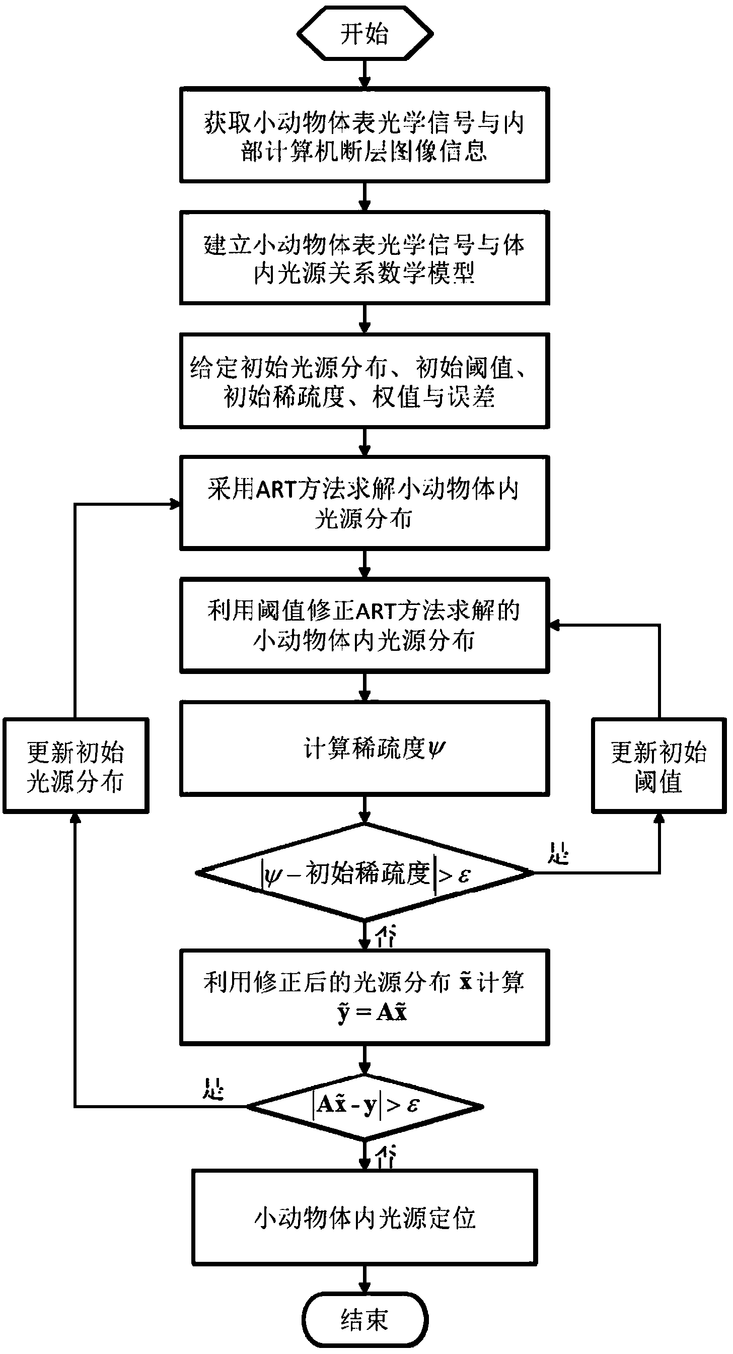
[0046] refer to figure 1 , the small animal bioluminescent imaging light source positioning method of the present invention comprises the following steps:

[0047] 1. Anesthetizing and immobilizing small animals

[0048] Anesthetize a small animal with a bioluminescence light source in the body, and fix the limbs, head and tail of the small animal on the sample holder.

[0049] 2. Obtain the optical signal and internal structure information of the small animal body surface

[0050]2.a In the darkroom, use the quantitative optical molecular tomography device disclosed in Chinese invention patent ZL201010173473.3 to first collect the fluorescent signals on the body surface of small animals, and collect them every 90 degrees. Four fluorescent images can be collected when the small animal rotates once. Image: On the premise that the postur...


PUM


Abstract

The invention discloses a method for positioning bioluminescence imaging light sources in small animal. The method is characterized by comprising the following steps: building a relation between body surface measured data vectors and in-vivo unknown light source distribution of the small animal by utilizing a quantitative optical molecular tomography device and a finite element method; computing the in-vivo light source distribution of the small animal by adopting an algebraic iterative reconstruction method; determining a threshold value according to sparseness, and performing correction on the light source distribution, obtained by adopting the algebraic iterative reconstruction method, by utilizing the threshold value; circulating for multiple times to finally obtain the in-vivo light source distribution of the small animal to realize the positioning of the bioluminescence imaging light sources. The method disclosed by the invention has the beneficial effects that the L0 normalization item does not need to be added to a mathematic model of the reconstruction problem, and approximation analysis does not even to be performed on the L0 norm by adopting the L1 norm and the Lp (0&1t; p≪ 1) norm, but the correction is performed on the light source distribution, obtained by adopting the algebraic iterative reconstruction method, directly by utilizing the sparseness. As norm approximation in the prior art is not adopted, the in-vivo light source positioning precision of the small animal is improved by the method provided by the invention.

Description

technical field [0001] The invention relates to an imaging light source positioning method, in particular to a small animal bioluminescent imaging light source positioning method, belonging to the field of optical imaging. Background technique [0002] Bioluminescent imaging technology uses luciferase gene to mark cells or DNA, and uses semiconductor cooling CCD camera to collect optical signals, which can directly monitor cell activity and gene behavior in living organisms. [0003] Bioluminescent imaging technology can also observe biological processes such as tumor growth and metastasis, infectious disease development, and specific gene expression in living animals. [0004] Bioluminescent imaging technology has the characteristics of no ionizing radiation, high sensitivity, and low cost, and is widely used in biological research. [0005] One of the core issues of bioluminescence imaging technology is the location of bioluminescent light sources in small animals, which ...

Claims


Application Information

Patent Timeline
IPC IPC(8): A61B5/00
Inventor 陈多芳梁继民朱守平陈雪利张瑞田捷
Owner XIDIAN UNIV
Learn More