Special cutting-width-variable three-edge milling cutter for grooving overall blade disk

A technology of integral blisks and three-sided blades, which is applied in the direction of milling cutters, milling machine equipment, manufacturing tools, etc., can solve the problems of non-adjustable blade position, difficult tool manufacturing, and inconvenient tool installation, so as to save installation time and reduce processing costs , Improve the effect of processing quality

Inactive Publication Date: 2014-05-07
HARBIN UNIV OF SCI & TECH
View PDF5 Cites 8 Cited by
  • Summary
  • Abstract
  • Description
  • Claims
  • Application Information

AI Technical Summary

Problems solved by technology

[0003] The purpose of the present invention is to provide a special variable cutting width three-sided blade milling cutter for slotting the whole blisk, so as to solve the problems of the existing three-side blade milling cutter for the slotting of the blisk, which is easy to wear, poor chip removal, and poor processing quality. , the position of the blade cannot be adjusted, the processing efficiency is low, the production cost is high, the tool manufacturing is difficult and the tool is inconvenient to install

Method used


Image

  • Special cutting-width-variable three-edge milling cutter for grooving overall blade disk
  • Special cutting-width-variable three-edge milling cutter for grooving overall blade disk
  • Special cutting-width-variable three-edge milling cutter for grooving overall blade disk

Examples


specific Embodiment approach 1

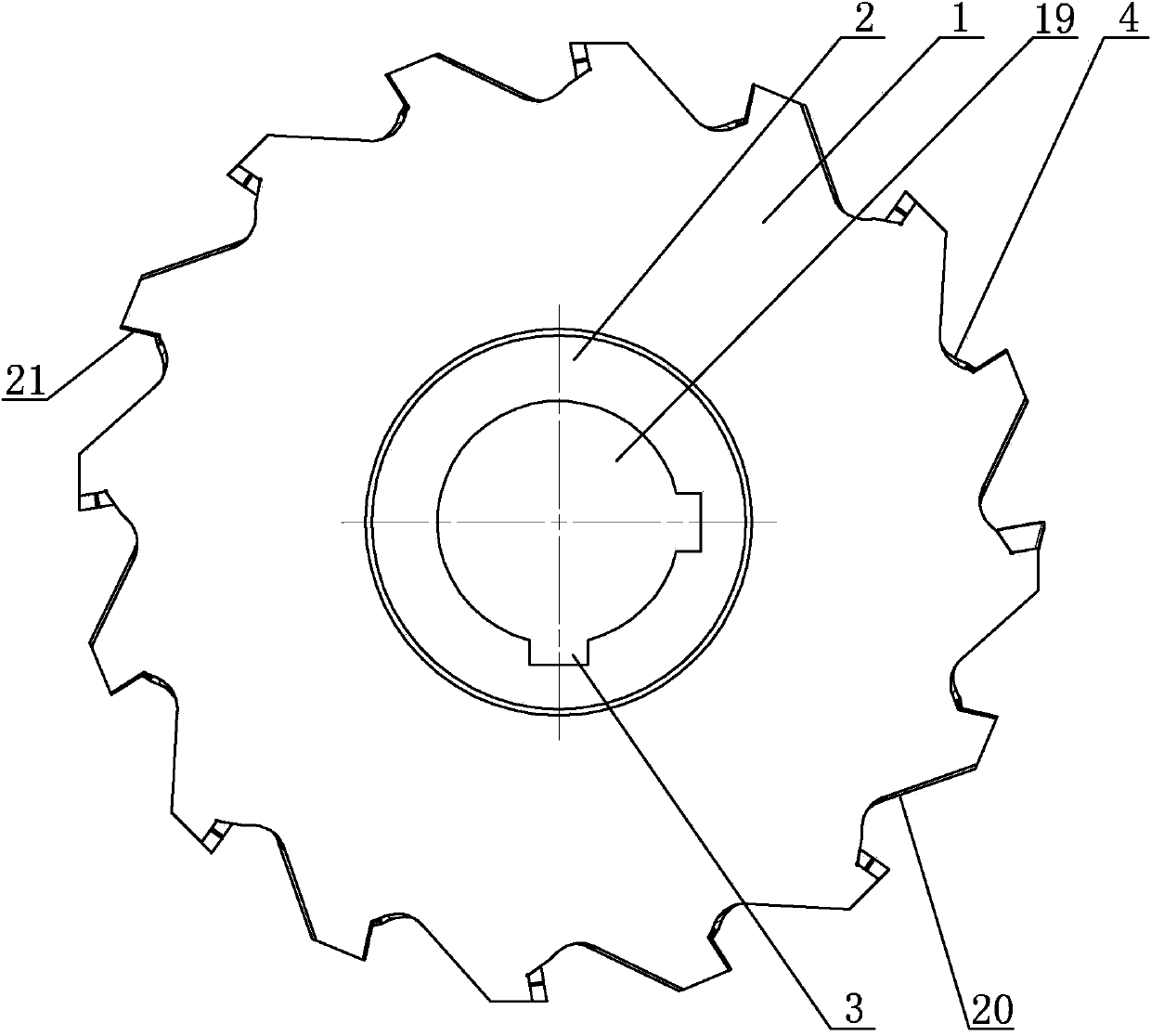
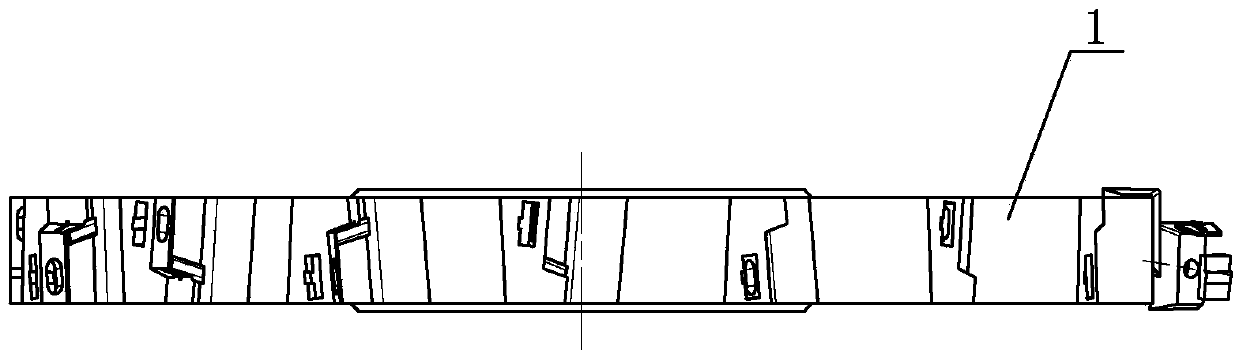
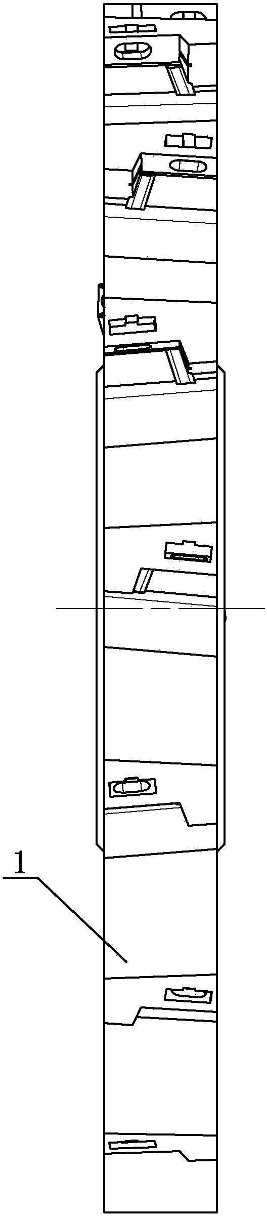
[0020] Specific implementation mode one: combine Figure 1-Figure 10 Illustrates that the variable-cut-width three-sided edge milling cutter dedicated to slotting integral blisks in this embodiment includes a cutter body 1, a central bushing 2 and N blades 6, the center of the cutter body 1 is provided with a central through hole 19, and the center The bushing 2 is located at the center through hole 19 of the cutter body 1, and at least one keyway 3 is processed axially on the inner wall of the center through hole 19 (for connecting and positioning with the drive shaft, and the milling key is installed in the keyway 3 through the key. The cutter is fixed on the drive shaft and positioned through the keyway 3), and N chip removal grooves 4 are uniformly processed on the outer peripheral surface of the cutter body 1, and the N chip removal grooves 4 are opened through the thickness of the cutter body 1, and N is an even number , and 16≤N≤22; the special variable-cut width three-...

specific Embodiment approach 2

[0030] Specific implementation mode two: combination Figure 4 and Figure 6 Note that the sipes 12 in this embodiment have preinstalled angles: that is, the axial relief angle is 24° to 26°, the radial relief angle is 14° to 16°, the axial rake angle is 4° to 6°, and the radial relief angle is 4° to 6°. The forward angle is 9°~11°. After the pre-installed angle is set, the size of the rake angle and rear angle of the blade can be reduced, and the strength and service life of the blade are increased. The undisclosed technical features in this embodiment are the same as those in the first embodiment.

specific Embodiment approach 3

[0031] Specific embodiment three: The radial rake angle of the special variable-cut width three-sided edge milling cutter for slotting the integral blisk described in this embodiment is 9-11°, the radial relief angle is 14-16°, and the axial rake angle is 4°. ~6°, and the axial relief angle is 9~11°. The angle after installing the blade with a front angle of 0° is the optimal angle range for processing the blisk of difficult-to-machine materials, which can effectively improve the service life of the tool. The undisclosed technical features in this embodiment are the same as those in the first or second specific embodiment.


PUM


Abstract

The invention discloses a special cutting-width-variable three-edge milling cutter for grooving an overall blade disk, belongs to the technical field of machining tools, and aims to solve the problems of tool abrasion, poor chip removal effect, poor machining quality, non-adjustable blade position, low machining efficiency, high production cost, large tool manufacturing difficulty and inconvenience in tool installation when the overall blade disk is grooved and machined by an existing three-edge milling cutter. A central bushing is fixedly arranged in a cutter body; N chip removal grooves are uniformly formed in the outer circumferential surface of the cutter body; two groove inner side surfaces of each chip removal groove are a large inclined surface and a small inclined surface; a cutter groove is formed in the small inclined surface of each chip removal groove; two adjacent cutter grooves are staggered; a threaded block groove is formed in the outer circumferential end surface of the cutter body; an elongated guide groove is formed in the side surface of each cutter groove; a blade is arranged in each cutter groove and is in fastened connection with a threaded hole of a threaded block through a fastening screw which penetrates into a fastening screw hole and each elongated guide groove; when each blade shifts for 0.5mm, 1.0mm or 1.5mm, a cushion block is arranged between each blade and the end surface of the corresponding cutter groove. The special cutting-width-variable three-edge milling cutter is used for grooving the overall blade disk.

Description

technical field [0001] The invention relates to a milling cutter with a three-sided edge for slotting an integral blisk, which belongs to the technical field of mechanical processing cutters. Background technique [0002] The overall blisk structure is complex, the blades are highly twisted, and the flow path is narrow and unobstructed. The blank is generally forged from difficult-to-machine materials such as titanium alloys and high-temperature alloys, and the manufacturing technology is difficult. The traditional grooving processing method usually uses a ball end milling cutter for line cutting or a cylindrical milling cutter for side milling. The processing efficiency is very low, and the tool wear is serious during the processing. Even, when the cutting process is subjected to a large radial cutting force, The knives would break, reducing productivity and increasing production costs. Three-sided milling cutters are widely used in machining. The common three-sided millin...

Claims


Application Information

Patent Timeline
Patent Type & Authority Applications(China)
IPC IPC(8): B23C5/02B23C5/12
Inventor 程耀楠张悦左殿阁陈天启
Owner HARBIN UNIV OF SCI & TECH
Why Eureka
Try Eureka