Grabbing, drilling and punching combined underground continuous wall grooving construction method

A combination of underground diaphragm wall and combination technology, which is applied in infrastructure engineering, artificial islands, water conservancy projects, etc., can solve the problems of small number of equipment, slow construction speed, high price, etc., and achieve fast construction progress, fast drilling speed, The effect of reducing the impact

Inactive Publication Date: 2014-05-07
SHANGHAI CONSTRUCTION GROUP
View PDF3 Cites 15 Cited by
  • Summary
  • Abstract
  • Description
  • Claims
  • Application Information

AI Technical Summary

Problems solved by technology

[0002] In recent years, underground diaphragm walls have been widely used in our country. Under the geological conditions where the upper part is soft soil and the lower part is rock strata, the construction methods for forming grooves in underground diaphragm walls mainly include: one is the method of using a slot milling machine. The number of equipment is very small, and the price is expensive; the other is to use a grab grooving machine combined with a drilling machine (or punching machine) for grooving construction, and use a grab grooving machine for construction on the upper soft soil, which is faster Fast and economical, but when forming holes in the lower hard rock formation, the construction speed is slow and the work efficiency is not high if the drilling machine (or punching machine) is used

Method used


Image

  • Grabbing, drilling and punching combined underground continuous wall grooving construction method
  • Grabbing, drilling and punching combined underground continuous wall grooving construction method
  • Grabbing, drilling and punching combined underground continuous wall grooving construction method

Examples


Embodiment Construction

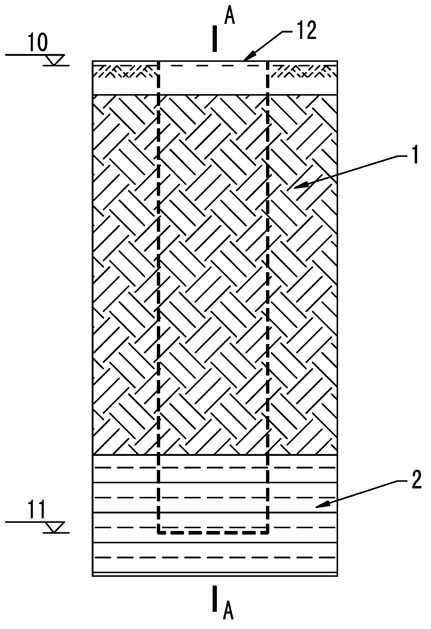
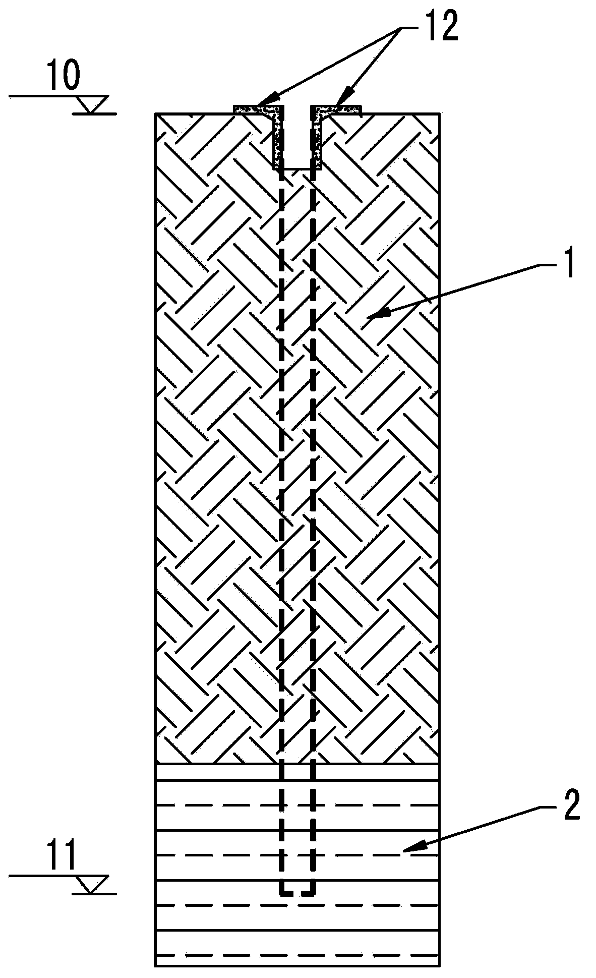
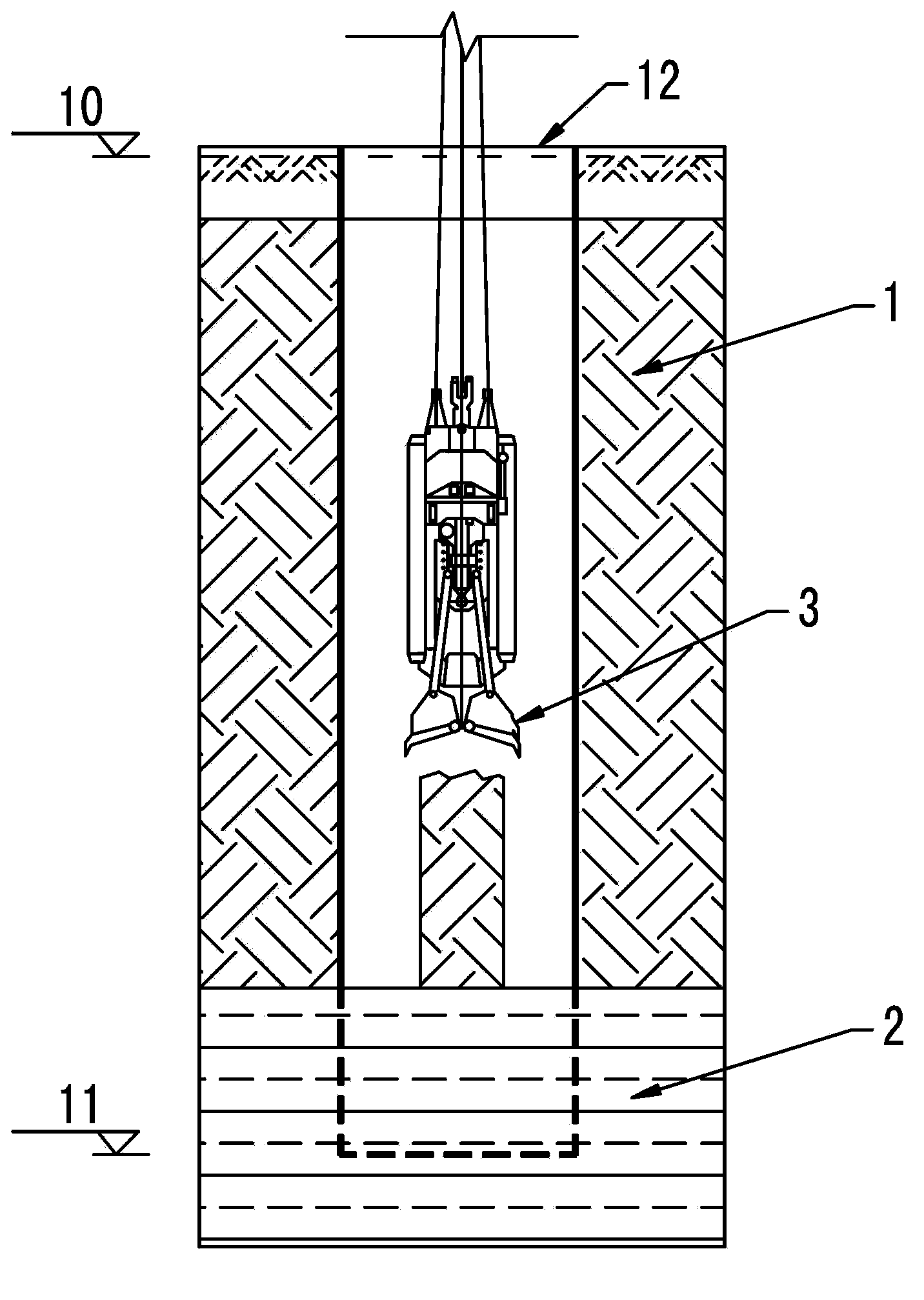
[0036] A kind of underground diaphragm wall groove-forming construction method combined with grasping, drilling and punching of the present invention will be further described in detail below.

[0037] The invention will now be described in more detail with reference to the accompanying drawings, in which preferred embodiments of the invention are shown, it being understood that those skilled in the art may modify the invention described herein and still achieve the advantageous effects of the invention. Therefore, the following description should be understood as the broad knowledge of those skilled in the art, but not as a limitation of the present invention.

[0038] In the interest of clarity, not all features of an actual implementation are described. In the following description, well-known functions and constructions are not described in detail since they would obscure the invention with unnecessary detail. It should be appreciated that in the development of any actual...


PUM


Abstract

The invention provides an underground continuous wall grooving method under the soft soil and rock stratum combined geological conditions. The underground continuous wall grooving method comprises performing preparation work, wherein the preparation work comprises measurement and positioning, wall guide construction, division of groove sections of the underground continuous wall and slurry preparation; grabbing and digging the upper portion soft soil in the groove sections after slurry is injected into the groove sections and enabling the slurry to be added into groove holes along with unearthing; performing drilling and cutting on bottom hard rock stratums in the groove sections; breaking up the drilled hard rock stratums through a square hammer punching machine and performing groove repair; performing hole cleaning and hole cleaning acceptance by a slurry circulation method. According to the grabbing, drilling and punching combined underground continuous wall grooving construction method, grabbing, drilling and punching are combined with each other, grooving construction is performed on the different hardness of rock stratums through different constriction machines under the condition that the quality of the underground continuous wall grooving construction is ensured, and accordingly the construction capability of various common machines is fully utilized and the construction progress and quality of grooving is ensured; the influence on the surrounding environment of the punching grooving vibration can be effectively reduced; an expensive underground continuous wall groove milling machine does not need to be utilized and accordingly the construction cost can be effectively reduced.

Description

technical field [0001] The invention relates to the field of building construction, in particular to a method for groove-forming construction of an underground continuous wall. Background technique [0002] In recent years, underground diaphragm walls have been widely used in our country. Under the geological conditions where the upper part is soft soil and the lower part is rock strata, the construction methods for forming grooves in underground diaphragm walls mainly include: one is the method of using a slot milling machine. The number of equipment is very small, and the price is expensive; the other is to use a grab grooving machine combined with a drilling machine (or punching machine) for grooving construction, and use a grab grooving machine for construction on the upper soft soil, which is faster Fast and economical and reasonable, but when forming holes in the lower hard rock formation, the construction speed is slow and the work efficiency is not high if the drilli...

Claims


Application Information

Patent Timeline
Patent Type & Authority Applications(China)
IPC IPC(8): E02D29/02E02F5/02
Inventor 周小溦徐平飞梅英宝钱智荣黄健昂
Owner SHANGHAI CONSTRUCTION GROUP
Why Eureka
Try Eureka