Hydraulic auxiliary device for parking

An auxiliary device and hydraulic technology, which is applied in the direction of parking buildings, building types, buildings, etc., can solve the problems of waste of cost and inconvenience, and achieve the effect of convenient use, simple structure and good adaptability

Inactive Publication Date: 2014-05-07
汪功明
View PDF6 Cites 4 Cited by
  • Summary
  • Abstract
  • Description
  • Claims
  • Application Information

AI Technical Summary

Problems solved by technology

This technical solution is installed on a car and can only be used by that car, not by other vehicles, which is very inconvenient and costly

Method used


Image

  • Hydraulic auxiliary device for parking
  • Hydraulic auxiliary device for parking
  • Hydraulic auxiliary device for parking

Examples


Embodiment 1

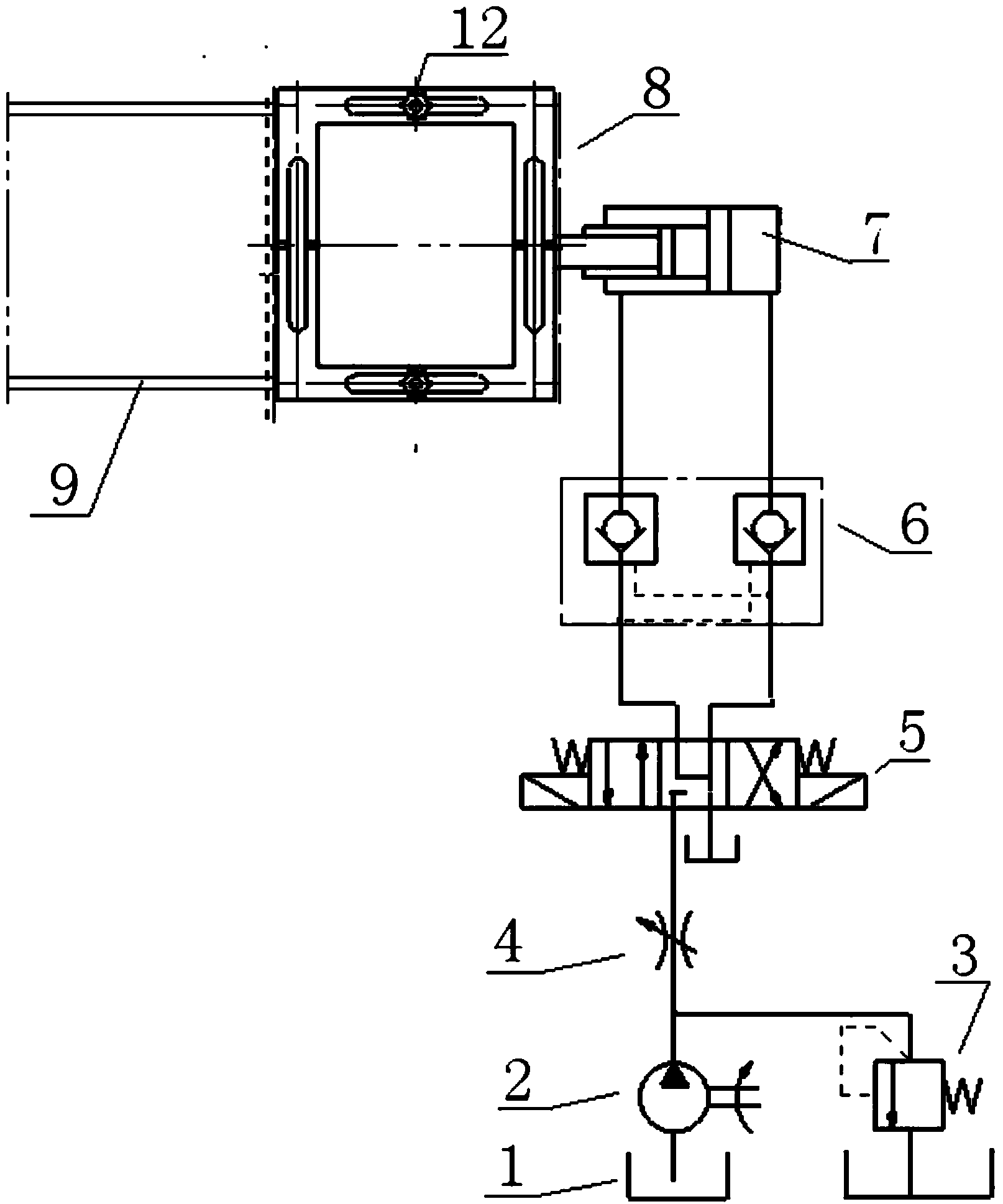
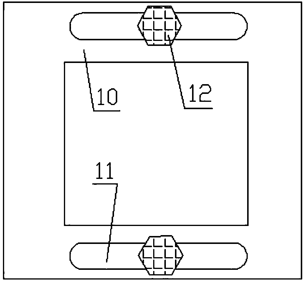
[0026] combine figure 1 , figure 2 , Figure 4 , one A parking hydraulic auxiliary device, including a fuel tank 1, a hydraulic pump 2, an overflow valve 3, a throttle valve 4, a three-position four-way electromagnetic reversing valve 5, a two-way hydraulic lock 6, a telescopic cylinder 7, a base 8, and a guide rail 9; 1 is connected to the hydraulic pump 2 pipeline, the throttle valve 4 is connected to the hydraulic pump 2 through one end of the pipeline, and the other end is connected to the three-position four-way electromagnetic reversing valve 5, and one end of the two-way hydraulic lock 6 is connected to the three-position four-way electromagnetic reversing valve The valve 5 is connected, the other end is connected with the telescopic cylinder 7, the piston rod of the telescopic cylinder 7 is connected with the base 8, the overflow valve 3 is connected with the oil tank 1 through one end of the pipeline, and the other end is connected with the output end of the hydra...

Embodiment 2

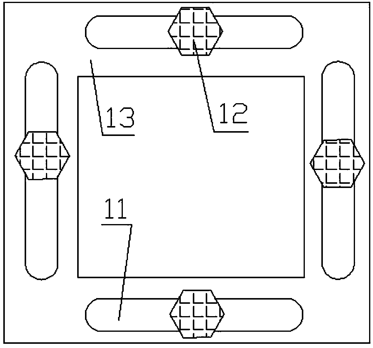
[0030] combine figure 1 , image 3 , Figure 5 , a parking hydraulic auxiliary device, including a fuel tank 1, a hydraulic pump 2, an overflow valve 3, a throttle valve 4, a three-position four-way electromagnetic reversing valve 5, a two-way hydraulic lock 6, a telescopic cylinder 7, a base 8, and a guide rail 9 The oil tank 1 is connected with the hydraulic pump 2 pipeline, the throttle valve 4 is connected with the hydraulic pump 2 through one end of the pipeline, the other end is connected with the three-position four-way electromagnetic reversing valve 5, and one end of the two-way hydraulic lock 6 is connected with the three-position four-way electromagnetic The reversing valve 5 is connected, the other end is connected with the telescopic cylinder 7, the piston rod of the telescopic cylinder 7 is connected with the base 8, the overflow valve 3 is connected with the oil tank 1 through one end of the pipeline, and the other end is connected with the output end of the hy...


PUM


Abstract

The invention discloses a hydraulic auxiliary device for parking. The hydraulic auxiliary device for the parking comprises an oil tank, a hydraulic pump, a throttle valve, a three-position four-way electromagnetic directional valve, a bidirectional hydraulic lock, a telescoping cylinder and a base. The oil tank is connected with the pipeline of the hydraulic pump; the throttle valve is connected with the hydraulic pump through one end of the pipeline; the other end of the throttle valve is connected with the three-position four-way electromagnetic directional valve; one end of the bidirectional hydraulic lock is connected with the three-position four-way electromagnetic directional valve; the other end of the bidirectional hydraulic lock is connected with the telescoping cylinder; a piston rod of the telescoping cylinder is connected with the base. The hydraulic auxiliary device for the parking disclosed by the invention is simple in structure, good in adaptability and convenient to use. Parking can be realized in a very small space, and meanwhile, parking space is also saved, and therefore, road-by parking is more orderly, standard and safer.

Description

technical field [0001] The invention relates to a parking auxiliary device, in particular to a parking hydraulic auxiliary device. Background technique [0002] With the rapid growth of the national economy, the number of cars in the city increases year by year, especially some families with more than two cars are very common. However, in some big cities where every inch of land is very expensive, there are very few extra spaces for people to park. With the rapid increase of the number of vehicles, the problem of urban parking has become increasingly prominent. In busy streets and crowded communities, on the one hand, the number of parking spaces is short and the supply is in short supply; And cause when vehicle enters and exits the parking space, scratches with the adjacent vehicles. With the side parking hydraulic auxiliary device, the parking on the road can be used in an orderly, standardized and safe manner. [0003] Chinese patent application number: 201120134484 d...

Claims


Application Information

Patent Timeline
IPC IPC(8): E04H6/42
Inventor 汪功明甘翠华汪蕾
Owner 汪功明
Why Eureka
Try Eureka