
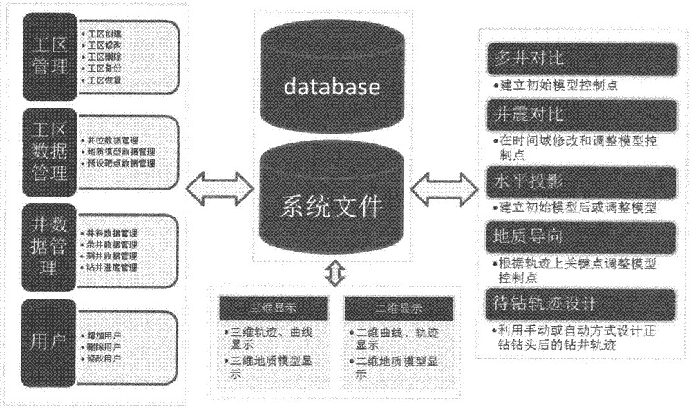
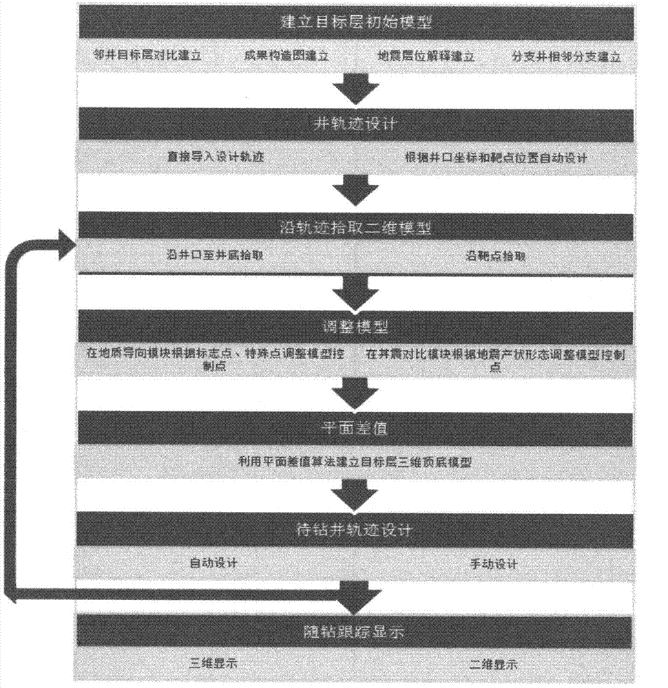
Horizontal well geosteering analysis method for designing track of well to be drilled through dynamic modeling during drilling

A drilling-while-drilling and drilling-encounter technology, applied in directional drilling, calculation, and special data processing applications, etc., can solve problems that cannot meet the needs of geological understanding while drilling, improve drilling efficiency, increase drilling-encounter rate, and save drilling costs Effect

Inactive Publication Date: 2014-05-07
刘俊
View PDF7 Cites 22 Cited by
  • Summary
  • Abstract
  • Description
  • Claims
  • Application Information

AI Technical Summary

Problems solved by technology

Current technology does not meet the needs of geological understanding while drilling
Moreover, a standardized geosteering analysis model has not yet been formed.

Method used


Image

  • Horizontal well geosteering analysis method for designing track of well to be drilled through dynamic modeling during drilling
  • Horizontal well geosteering analysis method for designing track of well to be drilled through dynamic modeling during drilling
  • Horizontal well geosteering analysis method for designing track of well to be drilled through dynamic modeling during drilling

Examples


Embodiment Construction

[0031] In order to make the technical problems, technical solutions and beneficial effects to be solved by the present invention clearer, the present invention will be described in detail below in conjunction with the accompanying drawings and embodiments. It should be noted that the specific embodiments described here are only used to explain the present invention, not to limit the present invention.

[0032] The first step is to establish the initial geological model of the target layer by using adjacent wells

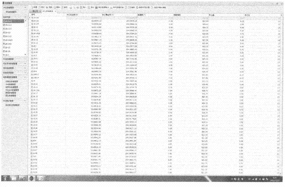
[0033] Data of adjacent wells (attached image 3 )

[0034] Location of adjacent wells on the map (attached Figure 4 )

[0035] The position of the control point of the target layer of the adjacent well (attached Figure 5 )

[0036] The top-bottom structural diagram of the target layer model generated by the plane difference algorithm (attached Figure 6 )

[0037] Cut out the model section along the trajectory (attached Figure 7 )

[0038] The second ste...


PUM


Abstract

The invention relates to a geosteering method for dynamic modeling during drilling and dynamic adjustment of the track in the process of horizontal well drilling of oil drilling. According to the solution, computer software is used, mutual multi-well comparison is carried out on target layer hierarchical data, target layer result structural maps, earthquake target layer pickup and multilateral well target layer data, and a plane difference algorithm is used, so that a target layer initial three-dimensional geological model is built; a two-dimensional geological model is extracted according to the track of a horizontal well which is being drilled, the direction of a drill bit is adjusted according to the spatial relation between the drilling track and the two-dimensional geological model, the vertical depth between the top and the bottom of the portion, arranged on each key point, of a target layer is obtained during drilling according to the electronic logging characteristics or the gasometry characteristics of special key points encountering a drill, such as a marker layer, a landing point, a bottom outlet, a bottom inlet, a top outlet, a top inlet and a special layer in the target layer, and the thickness uniformity principle, the three-dimensional geological model is adjusted, a two-dimensional geological model is extracted according to the track of the horizontal well which is being drilled, and the hole deviation angle of the drill bit is modified according to the dip angle provided by the two-dimensional geological model; the process is repeated, and it is ensured that the drilling direction of the drill bit is kept to be within the controllable range all the time. The hit rate and the drilling-encounter ratio of well drilling are improved, the drilling cycle is shortened, and drilling efficiency is improved.

Description

technical field [0001] The invention relates to a method for manually or automatically designing a trajectory to be drilled by dynamically establishing a geological model during the horizontal well drilling process, which is used to improve the target rate of the horizontal well and the drilling rate in effective target layers. In particular, it relates to a good method for judging the relationship between the drill bit and the target layer by using geological information while drilling and regional static geological data, and then correcting the drilling direction of the drill bit in advance. Background technique [0002] With the development of oil drilling technology, oil and gas reservoirs that could not be commercially developed in the past due to reasons such as thin oil layers and poor recoverable properties can now be exploited by drilling horizontal wells. Especially in recent years, the development of coalbed methane and shale gas has higher and higher requirements...

Claims


Application Information

Patent Timeline
IPC IPC(8): E21B7/04G06F17/50
Inventor 刘俊
Owner 刘俊
Learn More