Low-noise damping exhaust silencer
An exhaust muffler, low-noise technology, applied in muffler devices, machines/engines, engine components, etc., can solve the problems of environmental pollution, high noise, and large vibration of the muffler, and achieves reduced noise pollution, simple and compact structure, and increased manufacturing. cost effect
- Summary
- Abstract
- Description
- Claims
- Application Information
AI Technical Summary
Problems solved by technology
Method used
Image

Examples
Embodiment Construction
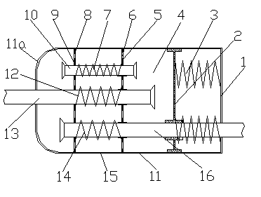
[0016] Accompanying drawing is the structure schematic diagram of the present invention, as shown in the figure: the low-noise damping type exhaust muffler of the present embodiment, comprises housing 11, intake pipe 13, expansion chamber 4 and exhaust pipe 16, in the expansion chamber 4 Facing the outlet of the intake pipe 13, a damping plate 2 is provided that is longitudinally slidable with the wall of the expansion chamber 4, and the damping plate 2 is positioned on the side opposite to the exit of the intake pipe 13 to provide a damping spring 3; the exhaust pipe 16 passes through the damping plate 2 and slide fit with it;
[0017] It also includes a moving partition 5 with a through resonance through hole 6, the air inlet pipe 13 and the exhaust pipe 16 pass through the moving partition 5 respectively, and the air outlet of the air inlet pipe 13 and the air inlet of the exhaust pipe 16 are divided. On both sides of the movable partition 5, the movable partition 5 coopera...
PUM
 Abstract
Description
Claims
Application Information
PatSnap Eureka turns technology decisions into work you can execute. Powered by our Innovation Knowledge Graph, it runs expert workflows across engineering, life sciences, materials and intellectual property. Get your review-ready output in minutes.


