Supercharge Your Innovation With Domain-Expert AI Agents!

Engine exhaust emission cooling device

A technology for cooling device and engine, which is applied to exhaust devices, engine components, machines/engines, etc., can solve the problems of complex system structure and narrow application scope, and achieve the effect of simple device structure, wide application scope and extended application scope.

Active Publication Date: 2014-05-07
MILITARY TRANSPORTATION UNIV PLA
View PDF4 Cites 4 Cited by
  • Summary
  • Abstract
  • Description
  • Claims
  • Application Information

AI Technical Summary

Problems solved by technology

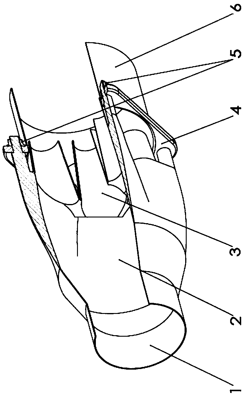
[0005] The purpose of the present invention is to provide an engine exhaust cooling device to solve the defects of narrow application range, complex system structure and negative effects in the prior art

Method used


Image

  • Engine exhaust emission cooling device
  • Engine exhaust emission cooling device
  • Engine exhaust emission cooling device

Examples


Embodiment Construction

[0016] In order to make the purpose, technical solutions and beneficial effects of the present invention more clear, the present invention will be further described in detail below in conjunction with the examples. It should be understood that the specific embodiments described here are only used to explain the present invention, and are not intended to limit the protection scope of the present invention.

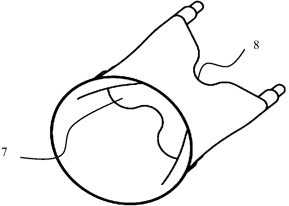
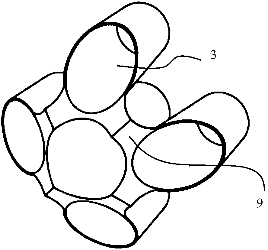
[0017] Such as figure 1 , figure 2 , image 3 As shown, the present invention provides an engine exhaust cooling device, which includes an expansion chamber, a diversion chamber, and a rear expansion chamber connected in sequence. The diameter of the front end pipe of the expansion chamber is the same as that of the engine exhaust pipe, and is the The exhaust pipe of the engine is connected upstream, the rear end pipe of the expansion chamber is a tapered expansion pipe, and is connected to the distribution chamber, the rear end of the distribution chamber is wave-shaped...


PUM


Abstract

The invention discloses an engine exhaust emission cooling device. The engine exhaust emission cooling device comprises an expanding room, a bypass room and a rear expanding room which are connected in sequence, wherein the diameter of a front end pipe of the expanding room is equal to that of an engine exhaust emission pipe, the front end pipe of the expanding room is connected with the upstream of the engine exhaust emission pipe, a rear end pipe of the expanding room is a conical expanding pipe and connected with the bypass room, the rear end of the bypass room is in a wave shape formed by sequential interval arrangement of convex surfaces and concave surfaces in equal numbers, and bypass pieces are tightly connected with an ejector pipe. The engine exhaust emission cooling device has the advantages that the cooling effects are remarkable, a large amount of air can be absorbed into exhaust by negative pressure generated by the device, and thereby, the exhaust temperature can be greatly lowered; the application range is wide, the device can use the constant temperature air in atmosphere as a cooling medium which is mixed with the exhaust without water or other cooling media, and the application of the range of the device is greatly widened; negative effects are absent, the exhaust resistance generated by the device can be reduced by a flow guide measure in the design, and therefore, the influence on engine performances can be avoided.

Description

technical field [0001] The invention belongs to the technical field of exhaust cooling equipment, in particular to an engine exhaust cooling device. Background technique [0002] If the exhaust temperature of the engine is too high and the temperature difference between the engine and the surrounding environment is too large, it is easy to show obvious infrared features, which is conducive to the detection and locking of military targets by infrared detection devices. Therefore, engines for military use need to reduce the exhaust temperature for concealment considerations. [0003] With the application of diesel particulate filter technology, the high-temperature exhaust during the regeneration of the particulate filter not only easily reduces the concealment of the engine, but also brings safety hazards to the surrounding environment, especially in flammable places. Foreign studies have been carried out on the cooling of the exhaust gas during the regeneration of the parti...

Claims


Application Information

Patent Timeline
Patent Type & Authority Applications(China)
IPC IPC(8): F01N3/05
Inventor 姚广涛张卫锋刘宏威资新运姜大海庞海龙张英锋
Owner MILITARY TRANSPORTATION UNIV PLA
Features
  • R&D
  • Intellectual Property
  • Life Sciences
  • Materials
  • Tech Scout
  • Unparalleled Data Quality
  • Higher Quality Content
  • 60% Fewer Hallucinations
Learn More