Shaft coupling mechanism and universal coupler thereof

A universal coupling and coupling technology, applied in the direction of couplings, elastic couplings, mechanical equipment, etc., can solve the problems of low running stability, poor bearing capacity, large flat key connection gap, etc., to improve the operation The effect of smoothness, reduction in the number of bolts, and small connection gap

Active Publication Date: 2014-05-07
CHONGQING UNIV
View PDF4 Cites 3 Cited by
  • Summary
  • Abstract
  • Description
  • Claims
  • Application Information

AI Technical Summary

Problems solved by technology

[0002] The coupling mechanism is a mechanical mechanism used to connect two shafts in different mechanisms to rotate together to transmit torque. Some coupling mechanisms also have the functions of buffering, damping and improving the dynamic performance of the shaft system. At present, many large The cross-shaft universal coupling mechanism used in steel mills and other metallurgical equipment generally has the following deficiencies: 1. The connection between the flanges at both ends of the cross-shaft coupling mechanism and the two axes of the working machine is through a flat key. Connected with bolts, it is difficult to install and align, often loose and requires a high number of bolts; second, the flat key connection has a large gap, and the matching connection is prone to impact due to the gap, large vibration, high noise, and low smooth operation; not only the bearing capacity is poor, Moreover, a large number of connecting bolts cause difficulty in installation and disassembly, high labor intensity and various processes, and the connecting fork is bulky, high in cost, takes up a large space and is not easy to manufacture

Method used


Image

  • Shaft coupling mechanism and universal coupler thereof
  • Shaft coupling mechanism and universal coupler thereof
  • Shaft coupling mechanism and universal coupler thereof

Examples


Embodiment Construction

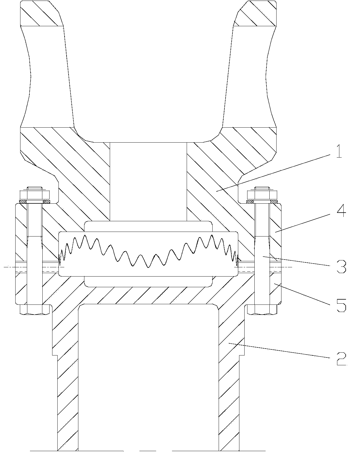
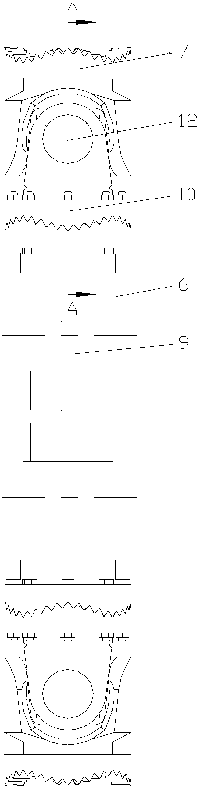
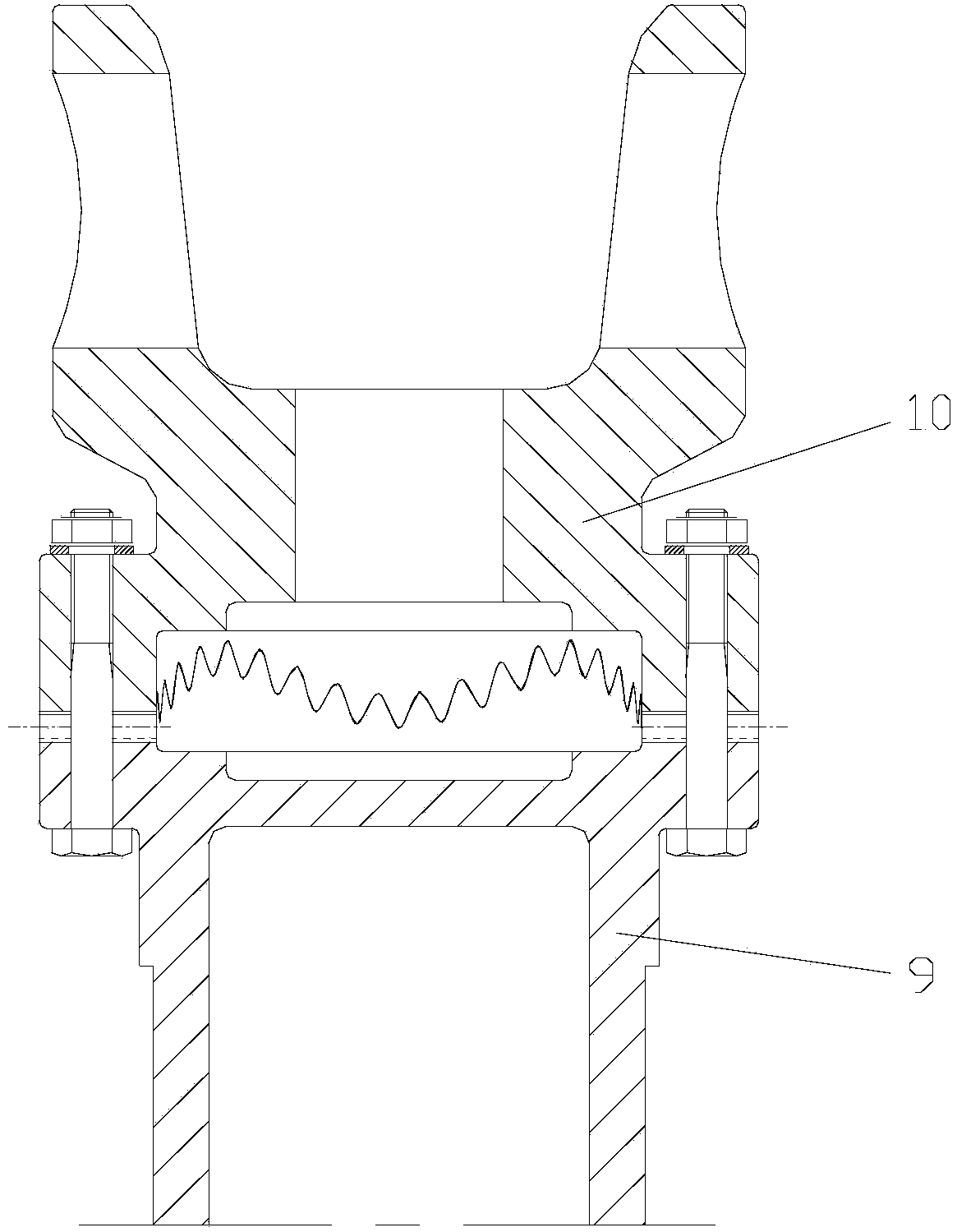
[0016] figure 1 It is a structural schematic diagram of the coupling mechanism of the present invention, figure 2 It is a structural schematic diagram of the universal joint of the present invention, image 3 for figure 2 Middle A-A sectional view, Figure 4 It is an exploded view of the universal joint of the present invention, as shown in the figure: the coupling mechanism of this embodiment includes a first rotating body 1 and a second rotating body 2 connected by end tooth meshing transmission; It is a curved end face tooth; as shown in the figure, a curved end face tooth is a kind of end face tooth whose tooth base surface forms a wave surface along the circular shear wave curve. The cooperation with the trough realizes secondary meshing and secondary centering. The contact area is large and there is a secondary load-bearing effect, which has a greater load-bearing capacity and can transmit torque greater than that of the same type of ordinary end-face gear coupling....


PUM


Abstract

The invention discloses a shaft coupling mechanism and a universal coupler thereof. The shaft coupling mechanism comprises a first rotating body and a second rotating body which are in transmission connection through engaging of end face teeth, wherein the end face teeth are curve end face teeth. The universal coupler comprises a transmission shaft, and an end face tooth jaw and a universal joint pin which are symmetrically arranged on two ends of the transmission shaft, wherein end face teeth of the end face tooth jaw are curve end face teeth. The shaft coupling mechanism and the universal coupler thereof have small connecting clearances with two shafts of a working machine; the deformation of a connecting surface can be reduced; the problems of large vibration, high noise and loosening at a coupling part after installation caused by the impact generated by the clearances are avoided; the stable level of operation is improved; the number of bolts is reduced; the volume of a link fork is reduced; the space is saved; the cost is reduced; the shaft coupling mechanism and the universal coupler thereof can be applied in special occasions with high temperature and heavy duty of a rolling mill, and can achieve the effects of strong bearing capacity, good centering performance, more stable operation, long service life, high transmission accuracy, low transmission noise, and capability of bearing heavier load with smaller volume.

Description

technical field [0001] The invention relates to a shaft connection structure, in particular to a shaft coupling mechanism and a universal shaft coupling thereof. Background technique [0002] The coupling mechanism is a mechanical mechanism used to connect two shafts in different mechanisms to rotate together to transmit torque. Some coupling mechanisms also have the functions of buffering, damping and improving the dynamic performance of the shaft system. At present, many large The cross-shaft universal coupling mechanism used in steel mills and other metallurgical equipment generally has the following deficiencies: 1. The connection between the flanges at both ends of the cross-shaft coupling mechanism and the two axes of the working machine is through a flat key. Connected with bolts, it is difficult to install and align, often loose and requires a high number of bolts; second, the flat key connection has a large gap, and the matching connection is prone to impact due to ...

Claims


Application Information

Patent Timeline
Patent Type & Authority Applications(China)
IPC IPC(8): F16D3/18
Inventor 林超赵相路
Owner CHONGQING UNIV
Why Eureka
Try Eureka