Plastic optical reflector for downlight with microlens array on surface

A microlens array and optical reflection technology, applied in the field of reflectors, can solve the problems of reducing diffuse reflection efficiency, limiting wide application, optical energy dissipation, etc., to achieve the effects of improving energy utilization, increasing irradiation area, and reducing glare

Active Publication Date: 2016-08-17
BEIJING UNIV OF CHEM TECH
View PDF8 Cites 0 Cited by
  • Summary
  • Abstract
  • Description
  • Claims
  • Application Information

AI Technical Summary

Problems solved by technology

The frosted diffuse reflection material has good diffuse reflection effect and is easy to manufacture, but due to the irregularity of its surface microstructure, there are inevitably a certain number of optical dead angles, and the light trapped in the dead angle will undergo optical energy dissipation, and part of the light energy will be converted Heat energy reduces the diffuse reflection efficiency; the diffuse reflection effect of the micro-foamed diffuse reflection material is good, and the diffuse reflection efficiency is high, but it is difficult to manufacture and the production cost is high, which limits its wide application

Method used


Image

  • Plastic optical reflector for downlight with microlens array on surface
  • Plastic optical reflector for downlight with microlens array on surface
  • Plastic optical reflector for downlight with microlens array on surface

Examples


Embodiment 1

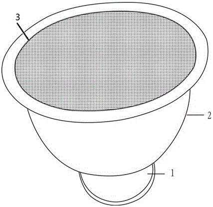
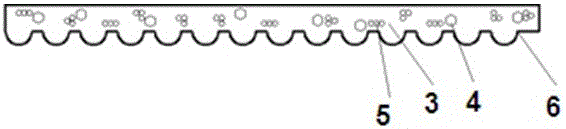
[0024] Such as figure 1 with figure 2 As shown, the plastic optical reflector for downlights with a microlens array on the surface of the present invention includes a light distribution port 1 and a light distribution cover 2, the light distribution port 1 is fixed on the bottom end of the light distribution cover 2, and the light distribution cover 2 is provided with Microlens Array Structure 3. The plastic optical reflector for downlights with a microlens array on the surface can be doped with light-reflecting particles 5 and ultraviolet absorbers 4, and the doping amounts of light-reflective particles and ultraviolet absorbers accounted for 5% and 0.5% by weight of the reflector respectively. %. The microlens array structure is a hemispherical structure 6 arranged in a rectangle, with a radius of 0.1 mm and a distance between centers of the spheres of 0.4 mm.

[0025] The material of the reflector is HIPS (high impact polystyrene), accounting for 93.82% by weight; the m...

Embodiment 2

[0027] The main difference between embodiment 2 and embodiment 1 is that the arrangement pitch of the prisms is different, the radius of the prisms is 0.1 mm, and the pitch between the centers of the prisms is 0.2 mm.

Embodiment 3

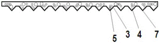
[0029] Such as image 3 As shown, the main difference between embodiment 3 and embodiment 1 is that the microlens array structure in embodiment 3 is prism structure 7, and the prism structure 7 is arranged in a rectangle, and the length of each side of the prisms is 0.1 mm, and the distance between centers is 0.4 mm.


PUM


Abstract

The invention discloses a plastic optical reflecting cover for a tube lamp with an lenticular array on the surface. The plastic optical reflecting cover comprises a lamp assembling port and a light distribution cover, wherein the lamp assembling port is fixed on the bottom end of the light distribution cover, the lenticular array structure is arranged in the light distribution cover, the lenticular array structure is a semispherical structure, a prism structure, a pyramid structure, a rectangular lens structure, a pyramidal structure, a semi-cylindrical structure, a semi-elliptical structure and a parabolic curve structure; the lenticular array structure is distributed in a triangular form, a regular hexagonal form, a rectangular form, a radiative form, a circular form and an elliptical form. By adopting the plastic optical reflecting cover, no optical dead corner exists, the light energy utilization rate is increased, and a purpose for increasing the light emitting efficiency and light emitting uniformity can be realized.

Description

technical field [0001] The invention relates to a reflector, in particular to a plastic optical reflector for a downlight with a microlens array on the surface. Background technique [0002] The downlight reflector is the "eye" of the downlight. It mainly controls the reflected light of the downlight and the efficiency of the downlight lamp. Its quality directly affects the irradiation effect. At present, downlight reflectors on the market are generally made of domestic aluminum and imported pure aluminum. The shape can be roughly divided into inner smooth spherical shape, inner pitted conical shape and curved surface shape with reflection convex and concave. The efficiency is poor, the glare is serious, the lumen utilization efficiency is low, the illumination is not enough, and the dead corners in dark areas often occur, and when the metal is rusted or stuck to dust, the reflection efficiency is greatly reduced. It is necessary to increase the number of installations to ac...

Claims


Application Information

Patent Timeline
Patent Type & Authority Patents(China)
IPC IPC(8): F21V13/04F21Y115/10
Inventor 吴大鸣高小龙郑秀婷刘颖许红赵中里刘言
Owner BEIJING UNIV OF CHEM TECH
Why Eureka
Try Eureka