
Heat radiator of light emitting diode (LED) lamp

A technology of LED lamps and radiators, applied in lighting and heating equipment, semiconductor devices of light-emitting elements, cooling/heating devices of lighting devices, etc., can solve the general heat dissipation effect of dense fins, increase material and production costs, and solve the Easily damaged and other problems, to achieve the effect of improving the performance of lamps, light weight and sufficient heat dissipation

Inactive Publication Date: 2014-05-07
HUNAN JIWEI ELECTRONICS SCI & TECH
View PDF9 Cites 2 Cited by
  • Summary
  • Abstract
  • Description
  • Claims
  • Application Information

AI Technical Summary

Problems solved by technology

Its main structure is most of the common embedded LED lamp structure in the existing market. Due to the general heat dissipation effect of the dense fin design, the application adds a fan to the lamp, but the fan design not only increases the material and production costs, but also It also increases the consumption of electric energy, and the lamp parts are easy to be damaged
So the design of the fan is actually a very impractical design

Method used


Image

  • Heat radiator of light emitting diode (LED) lamp
  • Heat radiator of light emitting diode (LED) lamp
  • Heat radiator of light emitting diode (LED) lamp

Examples


Embodiment 1

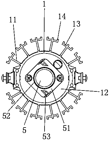
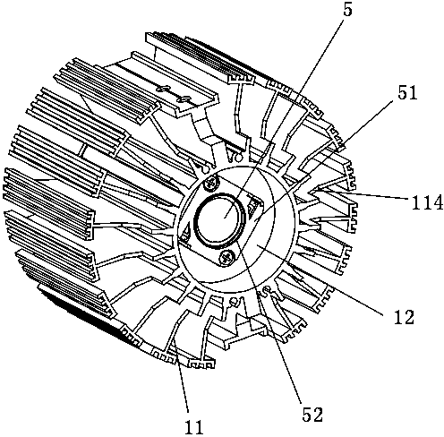
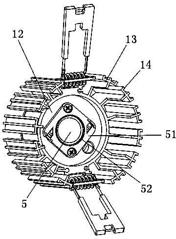
[0038] A heat sink for LED lamps, comprising a cylinder body 1, a main heat sink 11 arranged radially on the outer surface of the cylinder body 1, and a heat conduction plate 12 disposed inside the cylinder body 1, on which a light-emitting chip of an LED lamp is disposed on the heat conduction plate 12 , the outer end of the main heat sink 11 is perpendicular to the main heat sink 11 and is provided with a secondary heat sink 13 , and the outer surface of the secondary heat sink 13 is provided with a plurality of heat dissipation teeth 14 . The light-emitting chip includes a core board and a light-emitting surface 5 arranged on the core board. The light-emitting chip is covered with a calender 51, and the center of the calender 51 is provided with a through hole corresponding to the position of the light-emitting surface 5. The wall of the through hole protrudes forward to form a limiting ring 52 . When combined with other components of the lamp, the rear end of the reflector...

Embodiment 2

[0043] The difference from the above embodiment is that the heat dissipation teeth 14 are four evenly distributed on the arc-shaped plate, and the heat dissipation teeth 14 on both sides are flush with the two sides of the arc-shaped plate. The inner side of the main heat dissipation fin 11 extends forward to form an extended heat dissipation section. An inclined connection portion 114 is provided between the outer side of the extended heat dissipation section and the main heat dissipation fin 11 . A pier 113 is provided at the joint between the main heat sink 11 and the cylinder body 1 , and the thickness of the pier 113 is greater than that of the main heat sink 11 .

Embodiment 3

[0045] The difference from the above embodiments is that the outer side of the main heat sink 11 and the auxiliary heat sink 13 extend forward to form an extended heat dissipation section.


PUM


Abstract

The invention belongs to the lamp field, and particularly relates to a heat radiator of a light emitting diode (LED) lamp. The heat radiator of the LED lamp comprises a barrel, main cooling fins arranged on the outer surface of the barrel in radial mode, and a heat transfer plate arranged in the barrel, wherein a luminous chip of the LED lamp is arranged on the heat transfer plate, subsidiary cooling fins vertical to the main cooling fins are arranged at the outer ends of the main cooling fins, a plurality of heat dissipation teeth are arranged on the outer side faces of the subsidiary cooling fins, the main cooling fins and the subsidiary cooling fins are arranged in T shape, the luminous chip comprises a core plate and a luminous face arranged on the core plate, a light press plate is arranged on the luminous chip in covering mode, a through hole is formed in a position at the center of the light press plate, which is corresponding to the luminous face, and the hole wall of the through hole protrudes outward so as to form a limiting ring. The heat radiator of the LED lamp is low in height, few in used material, low in weight, and full in heat dissipation. Compared with an existing LED lamp heat radiator, when the heat radiator of the LED lamp is of the same volume as the existing LED lamp heat radiator, heat dissipation efficiency of the heat radiator of the LED lamp can be improved by 20%-30%, and power of the LED lamp can be improved by 3-6W, and furthermore use life of the LED lamp is long.

Description

technical field [0001] The invention belongs to the field of lamps, in particular to a radiator for LED lamps. Background technique [0002] The heat sink of the existing LED lamp adopts dense fin-shaped heat sinks. Due to the dense arrangement and slow heat dissipation, the heat dissipation effect is limited, and the existing LED lamp and the lampshade are connected by a protrusion with an external thread on the front end of the heat sink. Lift the connection section, and then connect the connection section to the lampshade for connection, the connection strength is low. Moreover, the distance from the radiator to the face of the lamp is long, the lamp body is long, and takes up a lot of space. The length of the lamp body also requires the height of the ceiling, so enough space must be made when making the ceiling, which is a waste of space. To sum up, the existing LED lamps have limited luminous power under the premise of limited heat dissipation effect, and cannot achiev...

Claims


Application Information

Patent Timeline
Patent Type & Authority Applications(China)
IPC IPC(8): F21V29/00F21Y101/02F21V29/77F21Y115/10
Inventor 周均朱海江郭云香胡浩张旭东
Owner HUNAN JIWEI ELECTRONICS SCI & TECH
Learn More