
Optical grating coupler and optical signal coupling method

A technology of grating coupler and light, which is applied in the field of optical communication, can solve problems such as limiting the application range of grating coupler, limiting the working wavelength of input light, and restricting the application of optical transmission, etc., and achieves the effect of simple structure, compatible process and high coupling efficiency

Inactive Publication Date: 2014-05-07
HUAZHONG UNIV OF SCI & TECH
View PDF2 Cites 39 Cited by
  • Summary
  • Abstract
  • Description
  • Claims
  • Application Information

AI Technical Summary

Problems solved by technology

[0003] However, the working bandwidth of the existing grating couplers is relatively small, which limits the working wavelength of the input light, thereby limiting the scope of application of the grating coupler and restricting the application of optical transmission

Method used


Image

  • Optical grating coupler and optical signal coupling method
  • Optical grating coupler and optical signal coupling method
  • Optical grating coupler and optical signal coupling method

Examples


Embodiment Construction

[0021] In order to further explain the technical means and effects of the present invention to achieve the intended purpose of the invention, the specific implementation and working principle of the grating coupler and the optical signal coupling method according to the present invention will be described below in conjunction with the accompanying drawings and preferred embodiments Describe in detail.

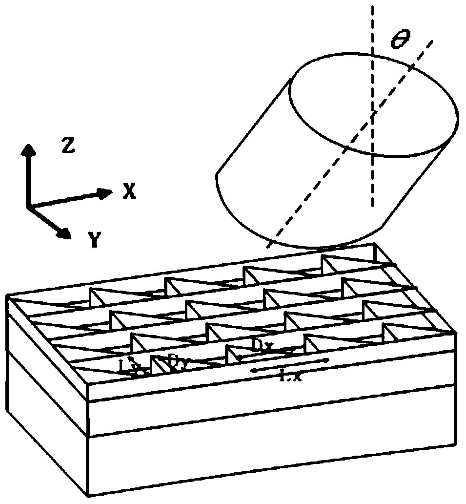
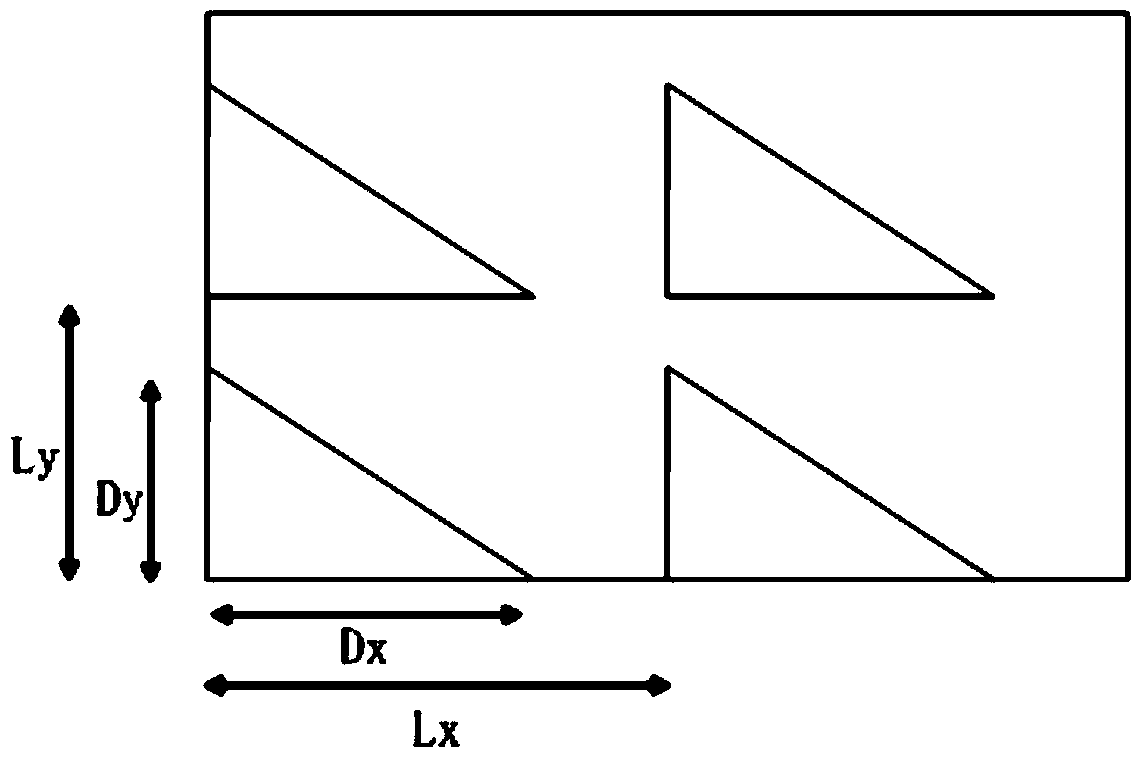
[0022] see figure 1 and figure 2 , the grating coupler provided by the embodiment of the present invention includes: a top silicon layer, a bottom silicon layer and a silicon dioxide layer; the silicon dioxide layer is above the bottom silicon layer; the top silicon layer is above the silicon dioxide layer; In the propagation direction of the light, the top silicon layer has an arrangement structure of at least two right triangles; the receiving optical fiber faces the arrangement structure of the right triangle, and the inclination angle θ of the receiving optical fiber is b...


PUM


Abstract

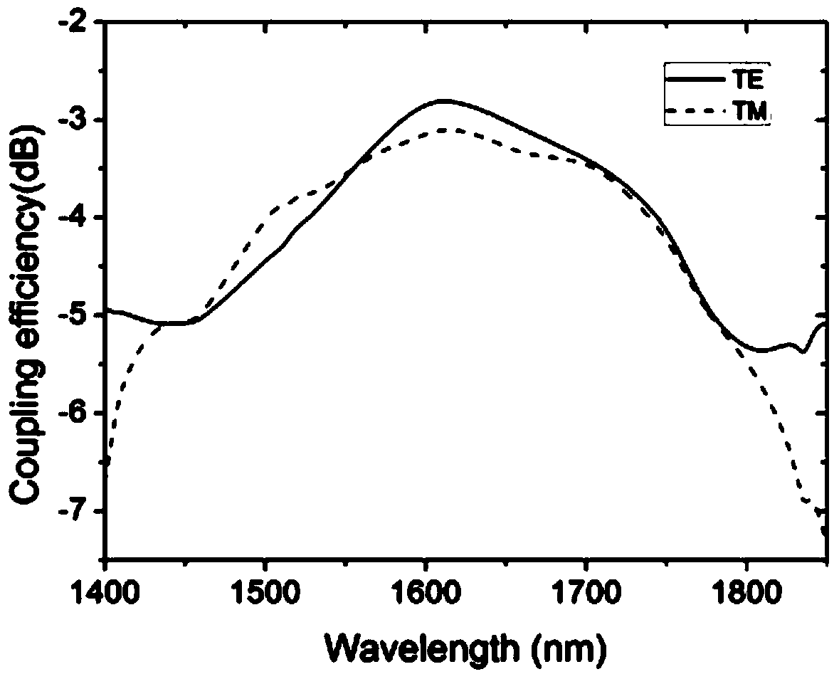
The invention relates to the technical field of optical communication and discloses an optical grating coupler and an optical signal coupling method. The optical grating coupler comprises a top silicon layer, a base silicon layer and a silicon dioxide layer, wherein the silicon dioxide layer is arranged on the upper surface of the base silicon layer, the top silicon layer is disposed on the upper surface of the silicon dioxide layer, the top silicon layer is of a structure formed by ranking at least two right triangles in the direction perpendicular to the light transmission direction, and received optical fibers face toward the rank structure of the right triangles. According to the optical grating coupler and the optical signal coupling method, through application of triangular optical gratings, work bandwidth of the optical grating coupler is increased, and applicability of the optical grating coupler is improved; besides, simulating calculation is performed through a three-dimensional time domain finite difference method so that TE and TM light coupling efficiencies are the same, optical grating structural parameters are determined, polarization insensitivity is achieved; the optical grating coupler has the advantages of being simple in structure, wide in work bandwidth, low in polarization loss and high in coupling efficiency.

Description

technical field [0001] The invention relates to the technical field of optical communication, and is mainly applicable to a grating coupler and an optical signal coupling method. Background technique [0002] Optical transmission has the characteristics of large bandwidth and high speed. Therefore, the combination of photon carrier and electronic carrier is an inevitable trend in the future development of information transmission. The efficient coupling between waveguide and optical fiber is the key to realize optoelectronic integration. The grating coupler has a simple structure, mature manufacturing process, and is easy to integrate, and is widely used in integrated optoelectronic devices and systems. [0003] However, the working bandwidth of the existing grating couplers is relatively small, which limits the working wavelength of the input light, thereby limiting the applicable range of the grating coupler and restricting the application of optical transmission. Conte...

Claims


Application Information

Patent Timeline
Patent Type & Authority Applications(China)
IPC IPC(8): G02B6/34
Inventor 张敏明周飞亚刘德明
Owner HUAZHONG UNIV OF SCI & TECH
Learn More