Method for detecting initial position of rotor of power robot

A technology of rotor initial position and detection method, which is applied to the control of generators, motor generators, electromechanical brakes, etc., and can solve problems such as unreliability, reduced accuracy, and dangerous lines of electric robots

Inactive Publication Date: 2014-05-07
SOUTHEAST UNIV
View PDF5 Cites 12 Cited by
  • Summary
  • Abstract
  • Description
  • Claims
  • Application Information

AI Technical Summary

Problems solved by technology

Whether the initial position of the rotor can be accurately estimated is a prerequisite for the high-performance control strategy (vector control or direct torque) of the permanent magnet synchronous generator and the realization of position sensorless operation. It is also related to whether the robot can start smoothly and whether it can realize The key issue of maximum torque starting; therefore, the detection of the initial rotor position has always been one of the hot and difficult issues in the engineering and technology circles, especially in electric robots, because the operation of the robot is basically a high-voltage operation, and the detection line is very Danger, if the initial position detection of the rotor is inaccurate, it will cause the electric robot to reverberate and rotate, and as a result, the entire power line and the robot may be damaged due to misoperation, and even cause a high-voltage short circuit in severe cases
[0003] There are two methods to ensure that the motor does not rotate and detect the initial position of the rotor. The current research results are di/dt detection method and high-frequency injection method. The di/dt detection meth

Method used


Image

  • Method for detecting initial position of rotor of power robot
  • Method for detecting initial position of rotor of power robot
  • Method for detecting initial position of rotor of power robot

Examples


Embodiment Construction

[0049] The present invention will be further described below in conjunction with the accompanying drawings.

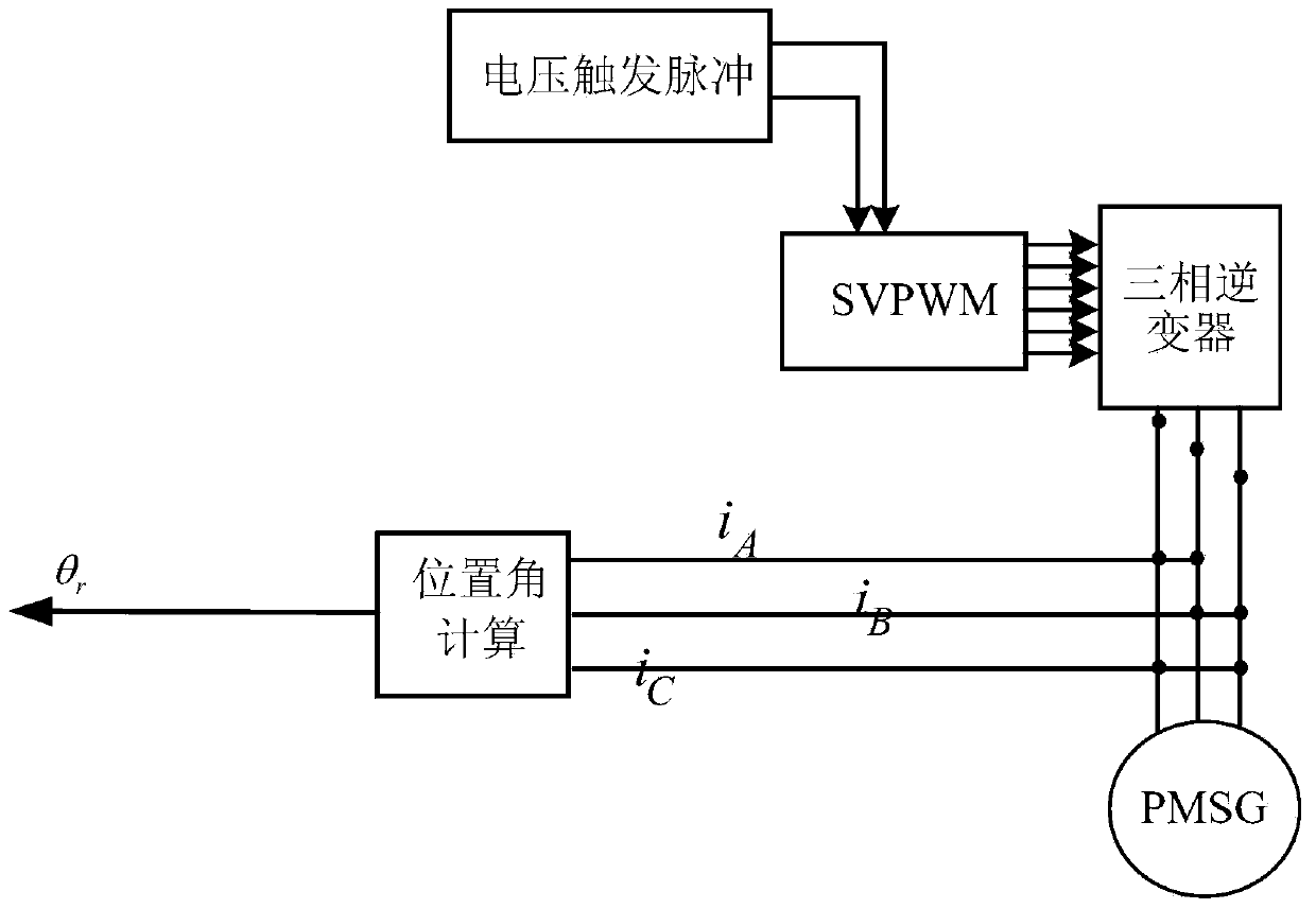
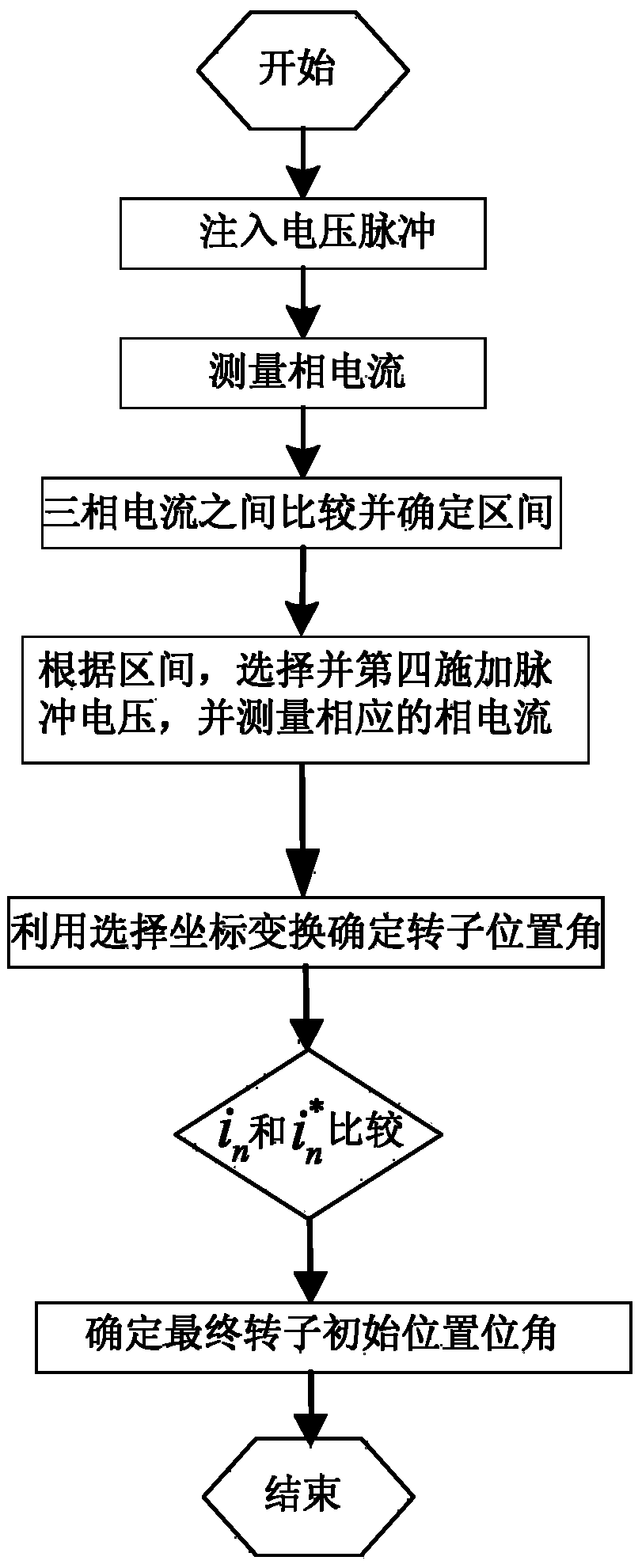
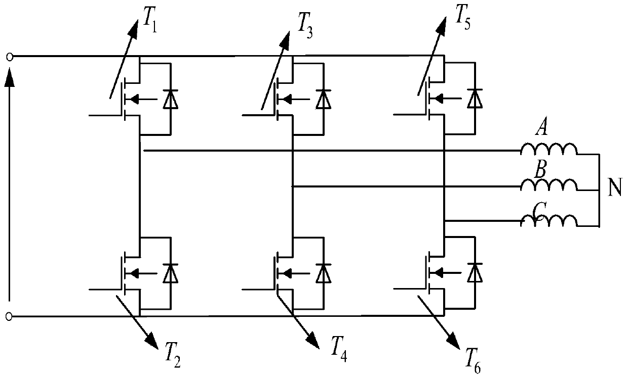
[0050] The method for detecting the initial position of the rotor of an electric robot first applies three different voltage pulses to the permanent magnet motor by controlling the three-phase inverter (drive circuit), according to figure 1 Detect the phase current response peak values ​​of phase A, phase B, and phase C respectively, and after comparing the phase current response peak values ​​of the three phases, preliminarily determine the range of the rotor position angle; then according to the range of the rotor position angle, control the three-phase The inverter applies a voltage pulse relative to the interval to the permanent magnet motor, and at the same time detects the corresponding peak current and compares it with the current peak value obtained from the previous three detections. During the four current peak detection processes, the optimal three detection ...


PUM


Abstract

The invention discloses a method for detecting the initial position of a rotor of a power robot. The method comprises the steps of firstly exerting three different voltage pulses on a motor by controlling a driving circuit, respectively detecting the phase current response peak values of the phase A/the phase B/the phase C, comparing the phase current peak values of the three phases, initially judging the section where the rotor is located, controlling an inverter to exert a voltage pulse relative to the section again according to the section where the rotor is located, meanwhile, detecting the current peak value of the phase, comparing the current peak value of the phase and the detected current peak value in the first step, selecting the three detection values in the four current peak value detecting processes for triangle function transformation, and finally determining the angle of the initial position of the rotor. The method for detecting the initial position of the rotor of a permanent magnet synchronous motor can detect the initial position of the rotor of the permanent magnet synchronous motor quite accurately, and achieve smooth starting of the motor, the implementation process is simple, any motor parameters are not required to be depended on, the measuring result is accurate, and the method has the high engineering practical value.

Description

technical field [0001] The invention relates to a method for detecting the initial position of a rotor of an electric robot. The initial position of the rotor is calculated by transforming rotating coordinates after detecting the current peak values ​​of phases A, B and C respectively. Background technique [0002] At present, in robot systems of various structures, the scheme of permanent magnet synchronous motor (PMSM) plays an important role because of its high efficiency. Especially in electric robots and small robots, PMSMs have been more used due to these advantages. Whether the initial position of the rotor can be accurately estimated is a prerequisite for the high-performance control strategy (vector control or direct torque) of the permanent magnet synchronous generator and the realization of position sensorless operation. It is also related to whether the robot can start smoothly and whether it can realize The key issue of maximum torque starting; therefore, the d...

Claims


Application Information

Patent Timeline
IPC IPC(8): H02P21/14
Inventor 余海涛孟高军胡敏强黄磊
Owner SOUTHEAST UNIV
Why Eureka
Try Eureka