Parallel gripper

A parallel gripper and gripper technology, applied in the directions of clamping, chucking, support, etc., can solve the problems of low working efficiency, high cost and complex action of the mechanical gripper, and achieve high-efficiency clamping of the hub. , low cost and simple structure

Inactive Publication Date: 2014-05-14
苏州久工自动化科技有限公司
View PDF6 Cites 14 Cited by
  • Summary
  • Abstract
  • Description
  • Claims
  • Application Information

AI Technical Summary

Problems solved by technology

[0003] Although the use of mechanical grippers can realize the clamping of the hub and can adapt to the clamping of parts of many sizes, it requires a special control system to realize the complex movements of the grippers, so the working efficiency of the mechanical grippers is relatively low, and the cost is high

Method used


Image

  • Parallel gripper
  • Parallel gripper
  • Parallel gripper

Examples


Embodiment Construction

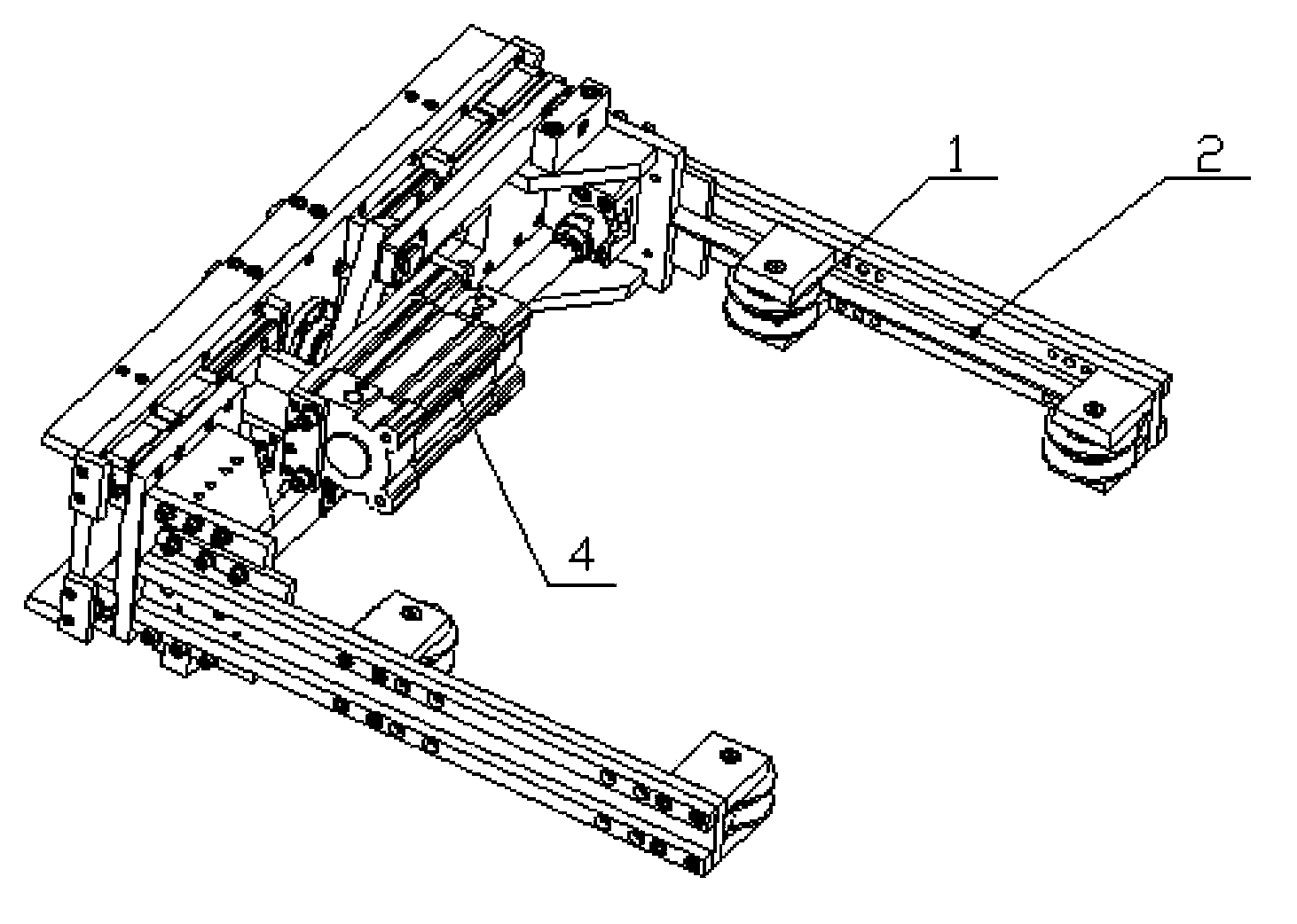
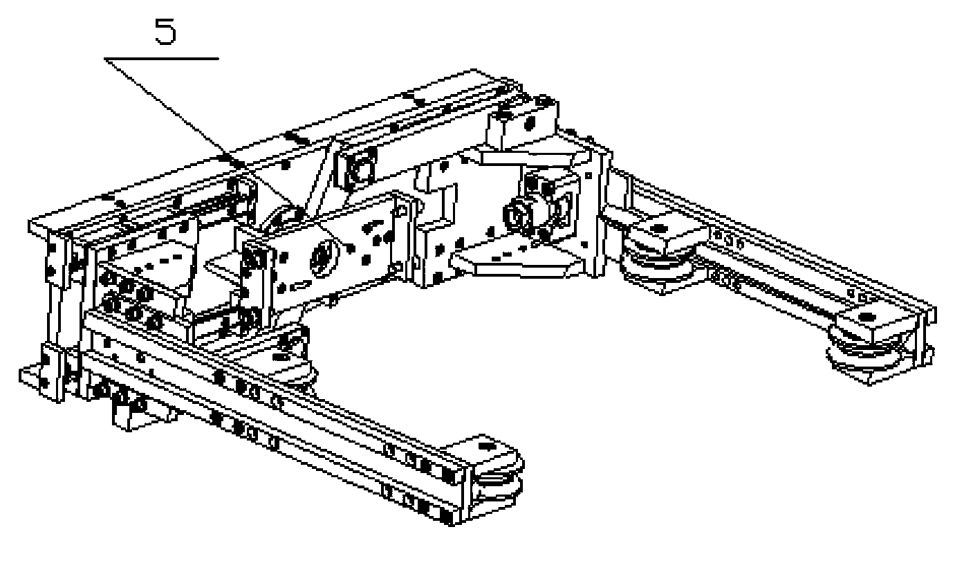
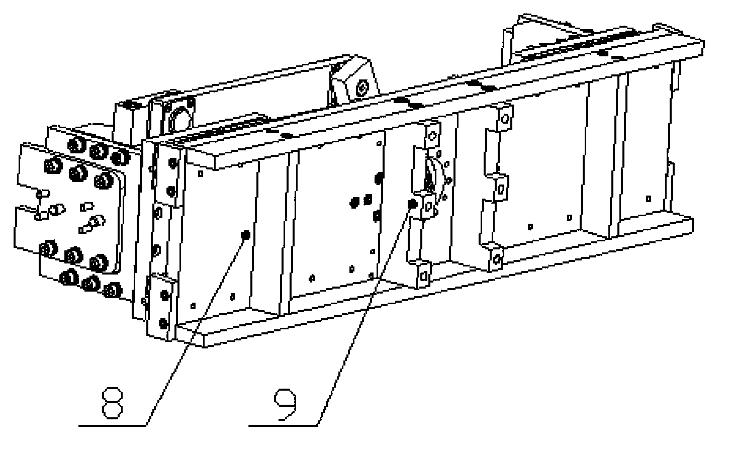
[0026] The invention discloses an effective parallel clamper. The parallel clamper has a simple structure, high reliability and high work efficiency under the premise of ensuring functional requirements and economic costs, and the mechanism is used as a The module can be quickly installed at the end of the robot arm without any changes to the existing structure.

[0027] The parallel clamper includes a base, a connection port arranged on the base, a pair of clamping beams, at least two rotating wheels respectively installed on the two clamping beams, a connecting block, and an air cylinder fixed on the base of the clamper The base, the cylinder installed on the cylinder base, the floating joint, and the center-symmetrical crank-slider mechanism installed on the holder base, the two clamping beams are respectively connected to the two ends of the center-symmetrical crank-slider mechanism through connecting blocks , the end of the cylinder is connected to the connection block th...


PUM


Abstract

A parallel gripper comprises a base, connecting ports arranged on the base, a pair of gripping beams, at least two rotating wheels respectively mounted on the two gripping beams, connecting blocks, a cylinder base fixed on the gripper base, a cylinder mounted on the cylinder base, a floating connector and a centrosymmetric slider crank mechanism mounted on the gripper base. The two gripping beams are connected to two ends of the centrosymmetric slider crank mechanism through the connecting blocks respectively, and the end portion of the cylinder is connected with the floating connector through the connecting blocks. The parallel gripper is simple in structure, high in reliability and low in cost, actions of gripping and loosening are completed by the aid of action of the centrosymmetric slider crank mechanism, and hubs can be gripped efficiently.

Description

technical field [0001] The invention relates to a component clamping device in a workshop, in particular to a parallel clamper. Background technique [0002] In the automatic production process of the hub, the effective clamping of the hub can quickly and accurately place the hub on the station to be processed, thereby greatly improving the production efficiency of the hub. At present, there are many kinds of clamping mechanisms that have applied for patents, but there are very few mechanisms that can be used to clamp parts of the shape of the hub. The method often used in the prior art is to use mechanical jaws to clamp the hub . The working process of the mechanical gripper is to first adjust the position of the gripper, and then open a certain angle relative to the size of the hub, grip the hub to achieve clamping, and send the hub to the station to be processed. [0003] Although the use of mechanical grippers can realize the clamping of the hub and can adapt to the cl...

Claims


Application Information

Patent Timeline
Patent Type & Authority Applications(China)
IPC IPC(8): B23Q3/00B25J15/00
CPCB23Q7/043
Inventor 雷恩·李·哈里森张淑云
Owner 苏州久工自动化科技有限公司
Why Eureka
Try Eureka